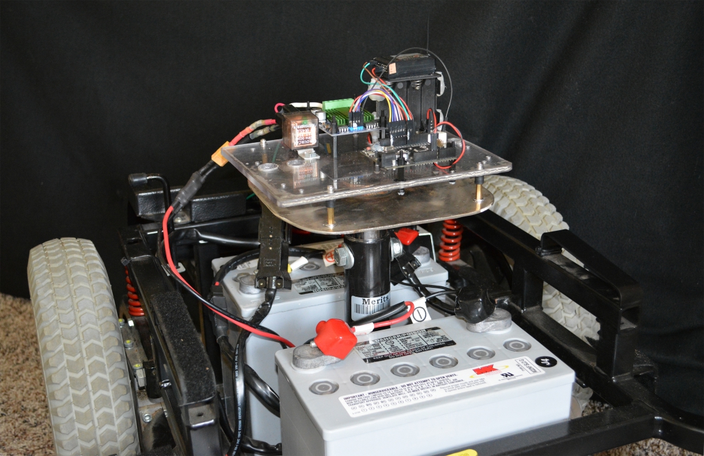
Today we introduce Rover 2! Rover 2 is one small step for our project, one giant leap in terms of utility. This robot frame is made to carry people, and in the USA, that’s often an ambitious proposition.
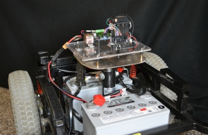
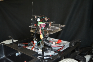
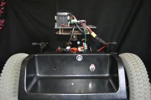
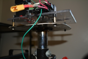
Enough talk, let’s jump into a photo essay showing the migration from lowly Rover 1 to mighty Rover 2.
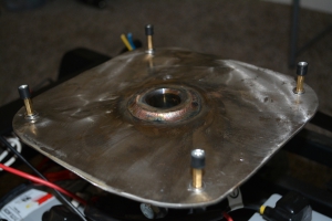
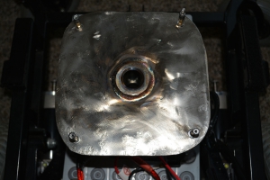
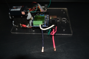
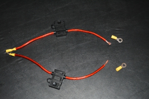
Question: what to do when you don’t have a 60 amp fuse holder laying around the shop and you need to fuse for 60 amps of current? We went for a hack: use two 30 amp fuses in parallel. I fully agree if you’re thinking that this is not an ideal move, but our alternatives were: 1. Wait for Maxi Fuse holder in the mail, or 2. Use unfused power source. Option #1 is out because our project must steam ahead, and option #2 is clearly a sin which could prove deadly. We went for the dual 30a fuse solution and it worked out fine.
Playing with Heat
We’ve previously talked about these curious heat shrink solder connectors. The last experiment with Rover 1 was so short-lived, I decided to give them another go with a little more current on the line.
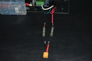
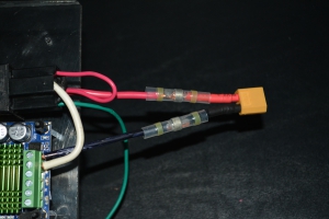
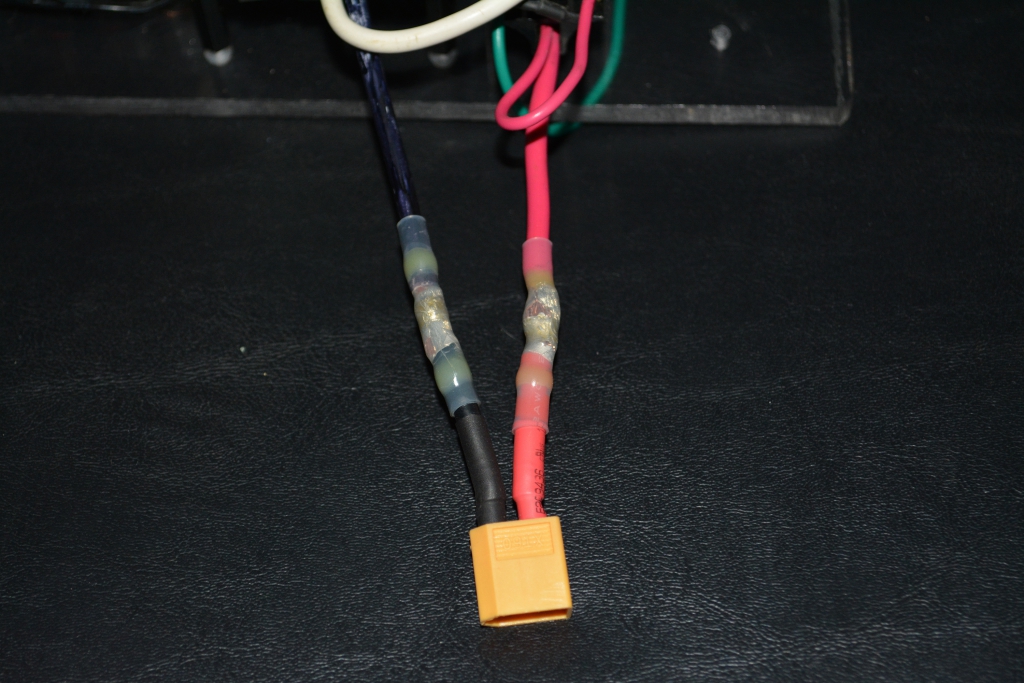
XT60 Connectors Are Great
If you’re planning numerous missions with your big robot, you’ll be charging it every day. You want to be able to easily plug up the charger. Here’s a simple solution: wire an XT60 connector in series to the power supply. I love these little connectors and I’ve never seen them have a failure of any kind. If you don’t have a few male/female sets in your bag, you can snag them reasonably off Amazon or eBay. Keep in mind 2 things when ordering:
- Double check that you’re ordering both male and female ends. You don’t want to purchase 5 pigtails, lose sleep eagerly anticipating their arrival in the mail, then receive the package and with horror find that they’re all male adapters.
- Keep an eye on the gauge (thickness) of wiring. For instance, in the Amazon link above you’ll see the first/cheapest pigtail results are for 14AWG (2.5mm) wiring. That may work for your application, but you may need 12AWG (4mm) pigtails if you’re pumping a ton of current — we specified 12AWG (4mm) in the eBay link, just to make the point about wire gauge.
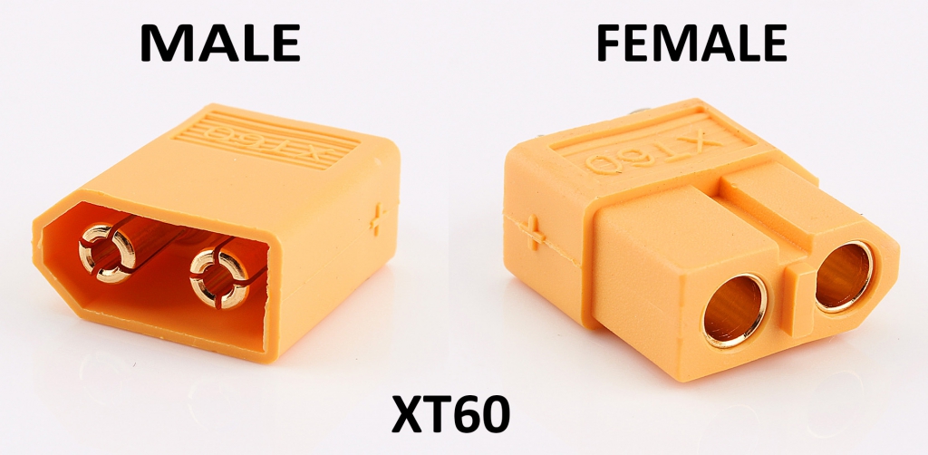
The picture above is presented in an effort to clear up any confusion about which end is male or female. I’m sympathetic to this confusion because the plastic shroud of either connector is the gender opposite of the inner metal connectors. Wow, this is creating more confusion. Let’s just stick with the picture above.
More Love Letters to the Electric Wheelchair
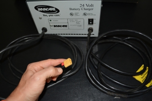
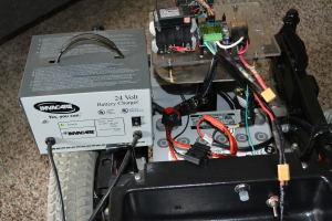
If you’ve been following this blog you know that I can’t stop raving about these wheelchair platforms. Here is another fun trick: cut the factory 3 pronged end off your wheelchair charger and solder/crimp a male XT60 adapter in it’s place. BAM! Just like that you’ve got a great charging system for your robot.
Mrs. Roby would really appreciate this kind of effusive praise directed her way a little more often. I know a lot of you engineer men out there are with me, right? Why is it so easy to talk at length about wheelchairs but writing 2 paragraphs to your sweetheart in a Valentines Day card seems like an insurmountable mountain?
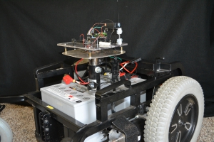
Wow, things just got way too deep. Let’s sign off with another series of pictures:
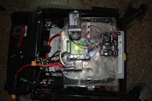
Wrapping Up
Let’s stop there and save the software and tuning for the next post.
Here’s a hint: sparks are going to fly.
Sincerely,
Roby


Leave a Reply