When the UPS guy drops off some new long-anticipated electronics component at your front door, you may be hit with two competing thoughts:
- First-date-level excitement about the capabilities of the new component and the possibilities it will open up for your projects
- Final-exam-level dread of the process of figuring out how to use the thing
#2 can be especially pronounced when you’re an early adopter and the internet hasn’t yet given birth to much documentation about your newly acquired component.
Since that fateful day in early 2018 when u-blox announced the ZED-F9P L1/L2/L5 GNSS receiver, I’ve logged an embarrassing count of visits to their website anticipating every new piece of information that they would publish about the little ZED.
Eventually u-blox announced they would call the official development board the C099-F9P. As an old-school believer in the technology maxim that you wait ’till the 3rd iteration of some new product before adopting, I had hoped that u-blox would quickly release a few updates to the dev kit so that I could feel like a wise old sage buying the more refined product.
Well, Digi-Key began selling the C099-F9P dev kit and I could only wait a month or so before caving in and buying two:
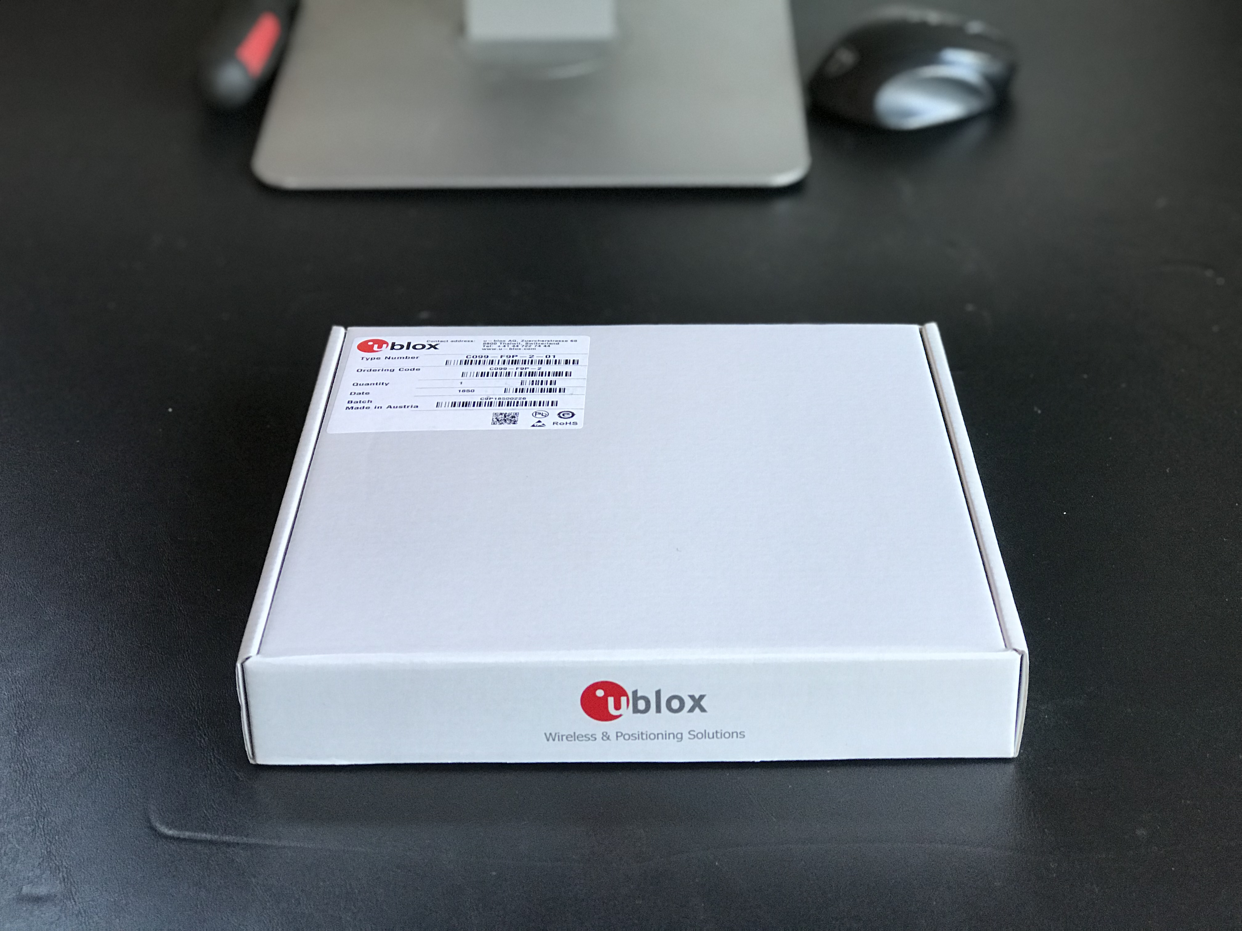
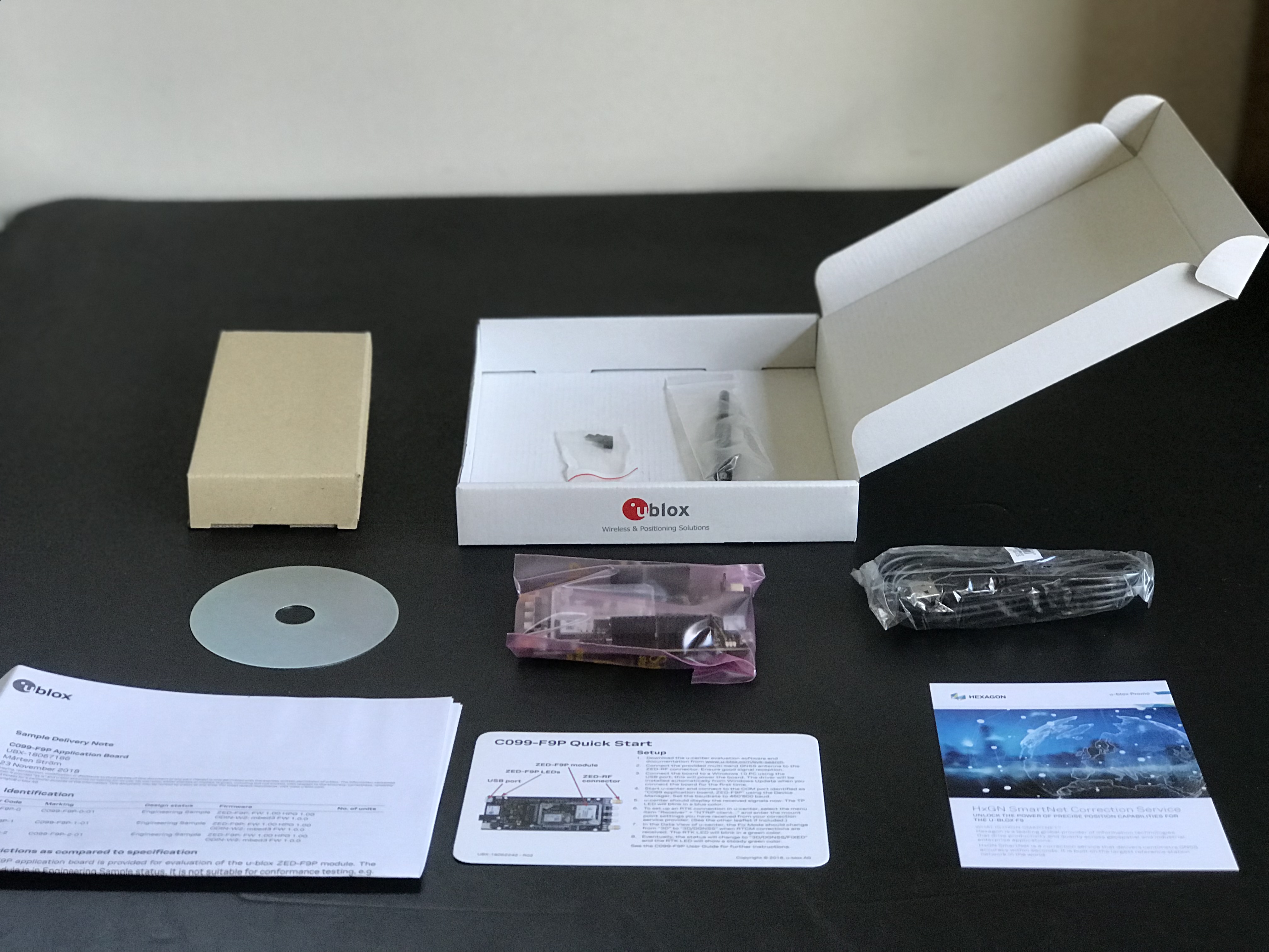
Unboxing the C099-F9P High Precision GNSS RTK Development Kit
When you unbox your C099-F9P, here’s what you’ll find:
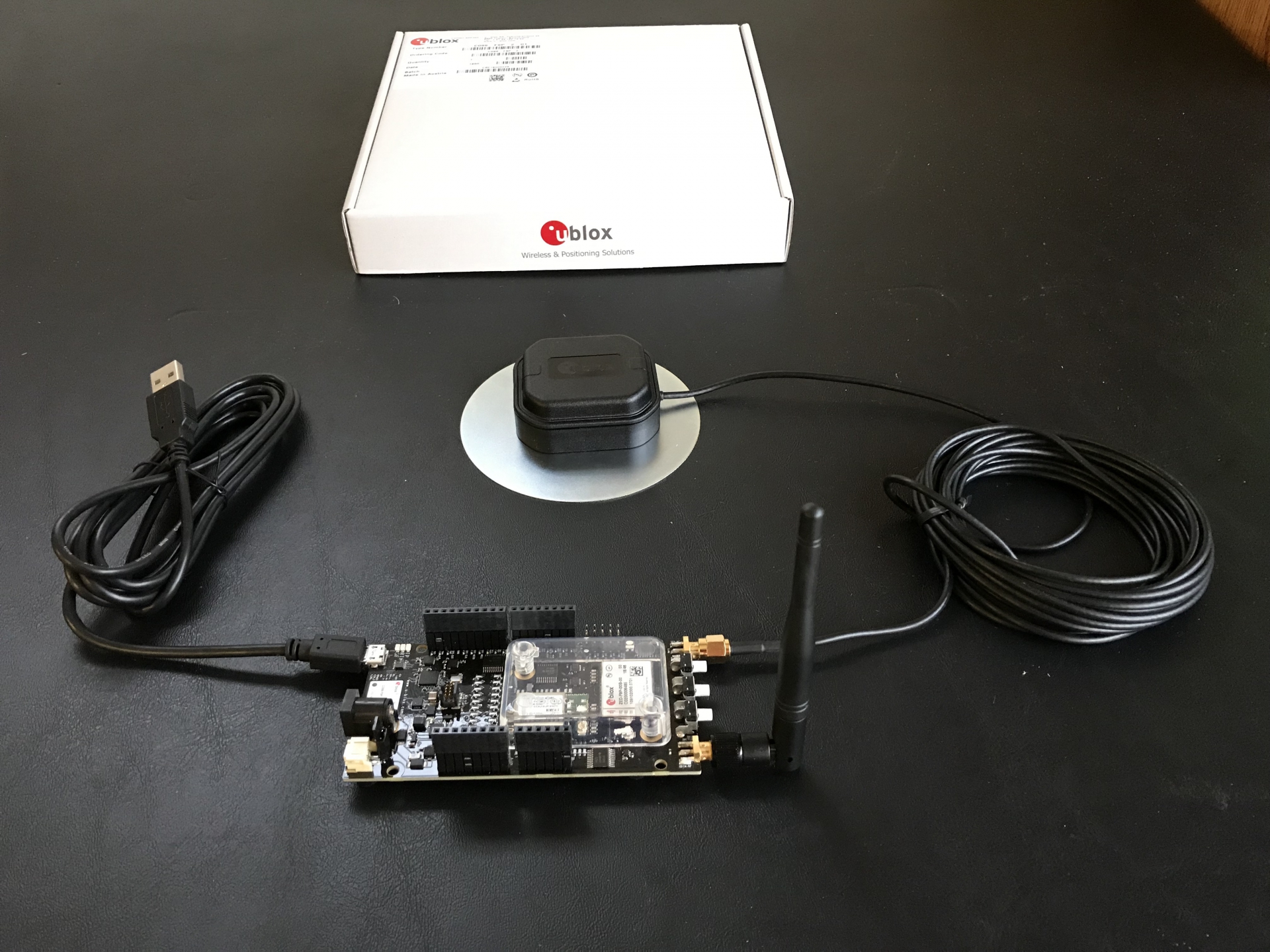
Hooking up the components yields this:
If you go on a late-night RTK GNSS wiki binge, you’ll likely have your brain numbed as you start to uncover the considerations involved in distilling the faint chirps from several dozen non-homogeneous satellites orbiting our planet 12,000 miles away into a centimeter accurate position in your front yard 20 times per second.
Let’s be clear: this blog post will not add to that scientific body of knowledge at all — instead, I’m assuming you’re a layman from some field other than RTK GNSS and you’ve stumbled across this ground-breaking technology as it’s effectively the only game in town for repeatable absolute centimeter-level outdoor positioning.
Those wishing to understand the technology underpinning RTK GNSS more deeply will find capable mentors in Tomoji Takasu[1], Clive Turvey[2], and Tim Everett[3].
Shortcuts to High Precision GNSS with the Revolutionary ZED-F9P (or “Early Adopter Tax Evasion”)
This blog post should serve as a crash-course in getting your ZED-F9P rolling. Success on my part will be measured in helping you avoid much of the early adopter tax that I had to dutifully pay through the usual fog of frustration and confusion that eventually gave way to the thrill of using a game changing component.
At this point I’m going to suggest something that (I think) you’ll eventually thank me for: Go ahead and buy two C099-F9P dev kits so that you can stand up your own Base Station. Trust me, at some point this will almost certainly feel like the best $250 USD investment you’ve ever made.
We’re going to set up one of the C099-F9Ps as the “Base Station” (to provide “Corrections”) and the other as the “Rover”. You have the option to use some local correction source if available, or to use a subscription correction service (i.e. the dev kit comes with a free trial subscription to a remote correction service called HxGN SmartNet — I’ve not used). Your mileage may vary, but I’ve never regretted setting up my own base station and relaying the RTCM corrections on a dedicated radio link.
Let’s start with the simplest possible use-case — hard-wiring the corrections output directly from the “Base Station” board to the “Rover” board (via a male-to-male breadboard wire). Once you have the setup running with a wired RTCM connection, you’re just a pair of 3DR radios away from a long-range wireless RTK setup.
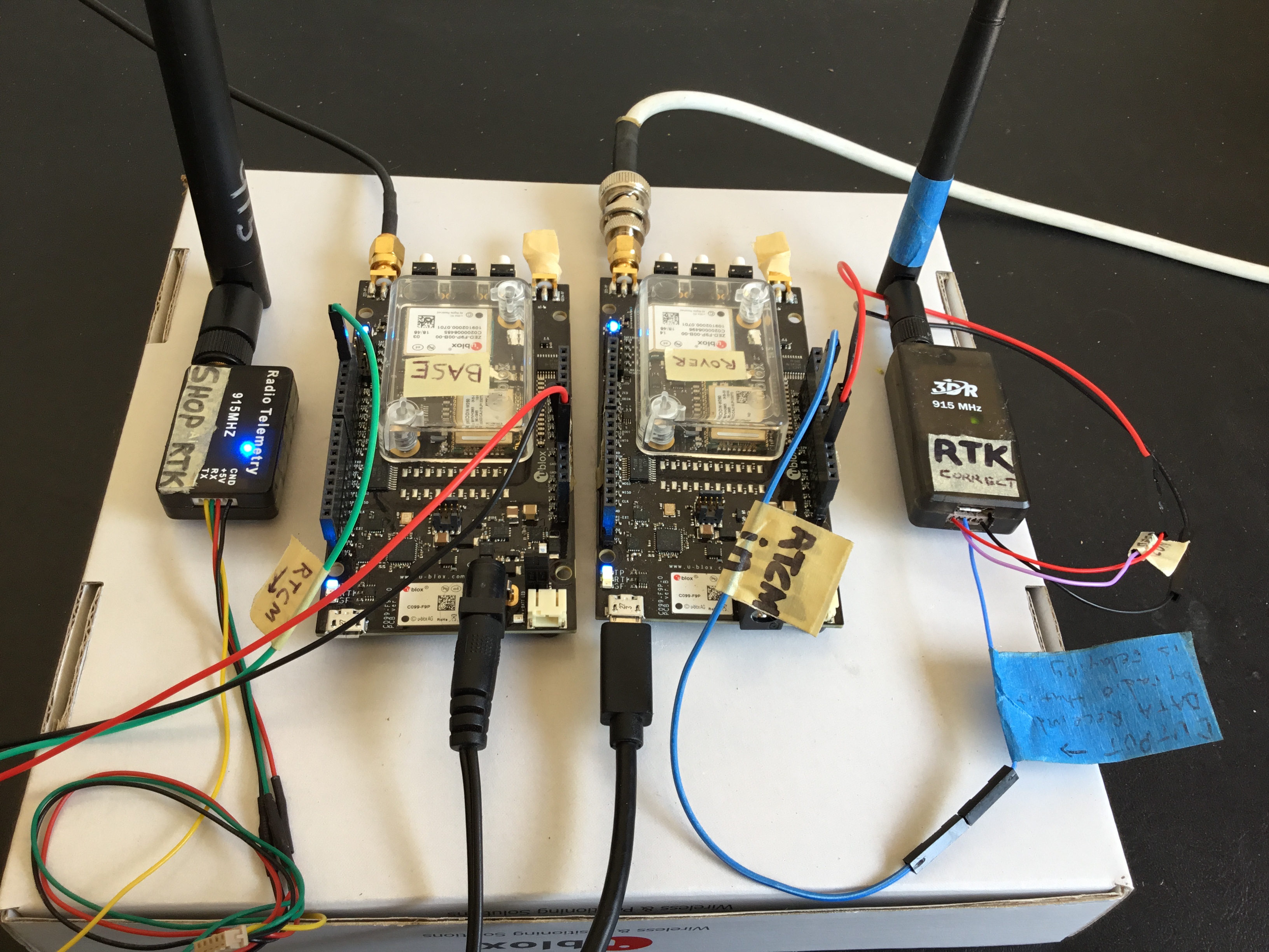
RTK success with two C099-F9P boards wired to each-other
Here are the high level items we’ll accomplish to get our self-contained RTK system running:
- Connect to your ZED-F9P from within u-center
- Update the ZED-F9P receiver firmware on both C099-F9P boards to the latest from u-blox
- Set up one C099-F9P board as the Base Station, one C099-F9P board as Rover, and wire RTCM output from Base Station to Rover
1. Connect to your ZED-F9P from within u-center
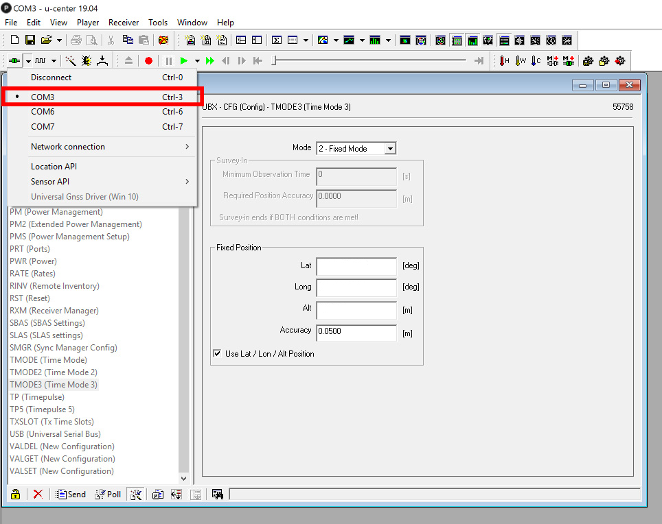
On Windows 10 (no knowledge if this procedure works on other versions of Windows), before you plug in the C099-F9P, open up the Device Manager and expand the Ports item. Now plug in the C099-F9P and you should see 3 new ports that appear — one for the ODIN-W2 radio (COM7 in the example below), one for the ZED-F9P (COM6 below), and a USB Serial Device port that’s apparently some kind of all-in-one port where you don’t have to guess baud rates correctly. It’s much easier IMO to use this port (COM3 below).
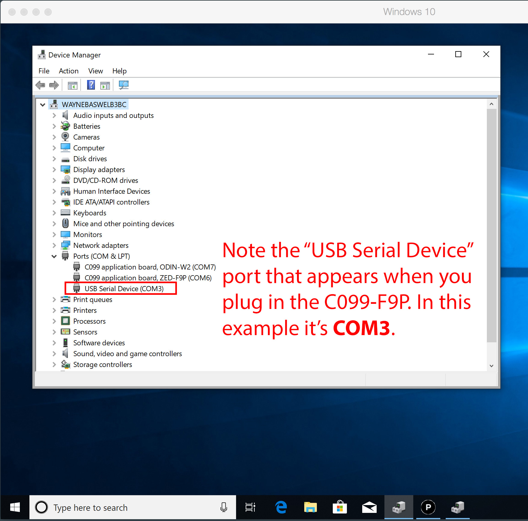
From within u-center (I’m using u-center 19.04 which is the latest as of May 2019), click the down arrow next to the port icon in the upper left and you should see a port number corresponding to the USB Serial Device you noted above (COM3 for me). Select this port and we’re now connected to the dev board.
2. ZED-F9P firmware update
Updating to the latest firmware may not be required, but it’s quick and easy — so I’d say go for it.
Here’s a little video I made of updating the ZED-F9P firmware.
3. Set up one C099-F9P as the Base Station, the other C099-F9P as the Rover, and wire RTCM output from Base Station to Rover
You’ll need to know your Base Station antenna’s coordinates to complete this section. If you’re not familiar with how to get those coordinates, check out Addendum 1 below.
The configuration procedure we follow in the video below configures the receiver to output NMEA PVT (Position, Velocity, Time) to the UART2 (June 2019 update: output on UART2 has been spotty — so I’m just using UART1 for PVT output) UART1 Tx port at 5Hz (i.e. a new reading every 0.2 seconds) at 115k baud. It also configures the UART2 Rx port to receive RTCM corrections at 115k baud. These settings are convenient for the mower rover we blogged about last time. Note that you can set the output rate up to 20Hz, but you may need to bump up the baud to something higher than 115k (otherwise the line may get clogged up and the readings would be delayed). On the slow rover we’re using to cut the grass, 5Hz is plenty and the Pixhawk 4 we’re using communicates nicely at 115k baud.
If you’ve followed the steps above, then you can easily send RTCM correction data from the Base Station to the Rover by connecting the the Base Station UART1 Tx to the Rover UART2 Rx with a simple breadboard wire.

Caveat: the one-wire approach will work if you’re powering both boards with an electricity source with a common ground. If not, you can just connect the two boards’ GND sockets together (you’ll find multiple GND sockets on the dev board) with another breadboard wire.
It wasn’t obvious to me from the documentation which sockets on the C099 board map to UART1 and UART2 — perhaps all other humans were born with this knowledge. Here’s a little mapping diagram that will hopefully help future travelers:
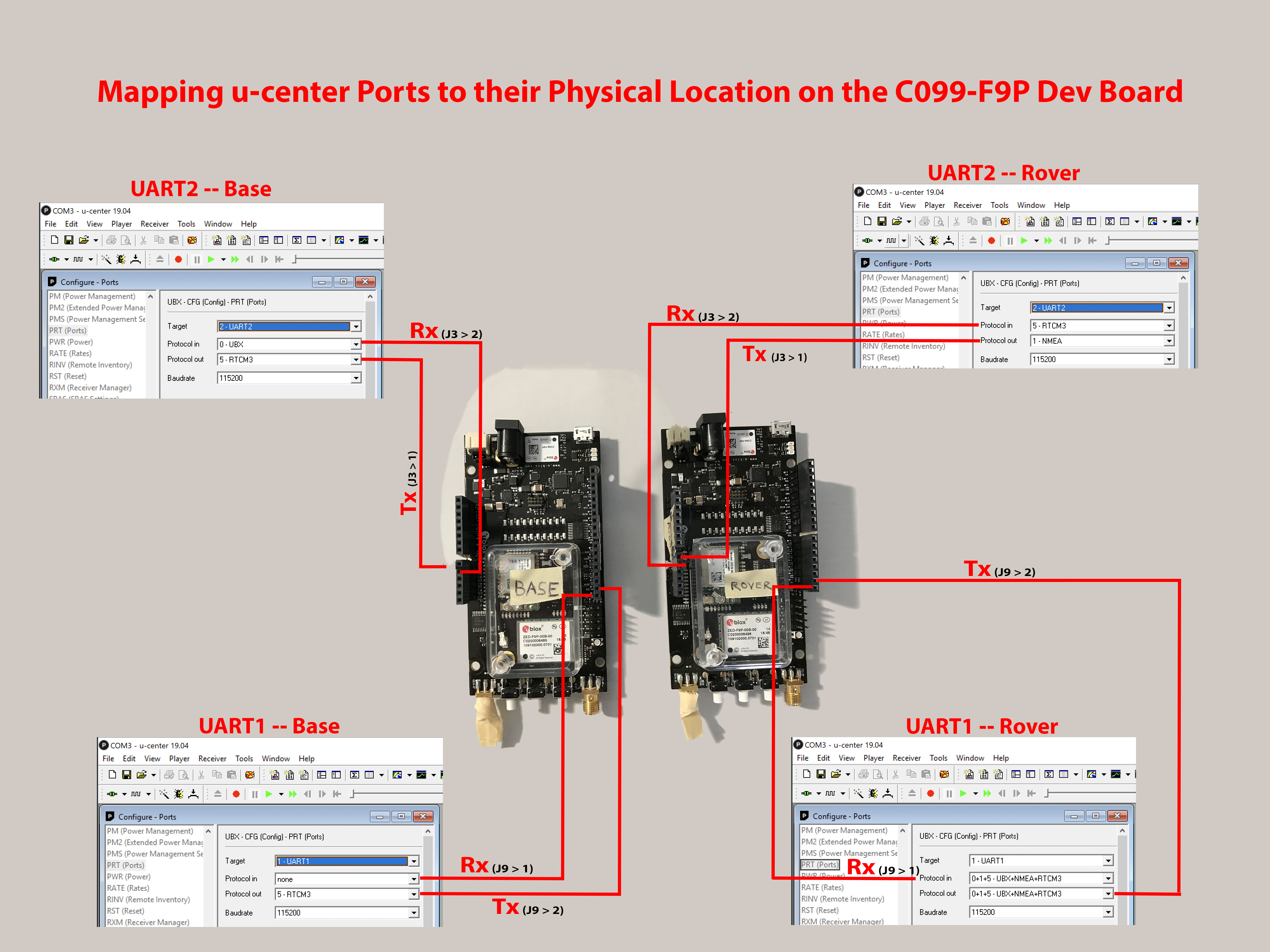
You’ll note that we’ve taped off the ODIN radio antenna jack (remember that I don’t use the on-board ODIN radio). This just gives me one less thing to remember when connecting the GNSS antenna to the dev board.
ZED-F9P real world performance demonstration
Here’s a little video showing why this small RTK receiver is so significant:
Rolling our own long-range corrections link
If you’ve been using u-blox high precision gnss components since the NEO-M8P, then you may have previously used the superbly easy-to-use and capable C94-M8P development kit for that (L1-only) module[4]. The C94-M8P basically did everything right from an ease-of-use standpoint for a builder wishing to probe that gnss module’s functionality. For instance, the development kit was sold as a pair of modules (i.e. so that you weren’t tempted to skip setting up your own local base station), the radio was based on SiK telemetry achieving great range, and the procedure for setting up a base station / rover system was very simple and well documented[5].
I spent several unrecoverable hours trying to get two C099-F9Ps to communicate with each-other via the on-board ODIN-W260 radio. Efforts tried include downloading multiple versions of the s-center radio evaluation software, feverishly googling for any kind of documented success story setting up the link, setting jumpers, and flashing various firmwares and configuration settings to the dev board. I’m not sure if you’d describe my efforts as total failure or absolute failure, but I never saw any sign that I was close to actually making the communication link work.
Fortunately, long-range radios have become very cheap in recent years, so snag a pair off eBay, Amazon or SparkFun and you’ll have a long-range RTCM corrections link between the Base Station and Rover with minimal effort.
3DR radio configuration
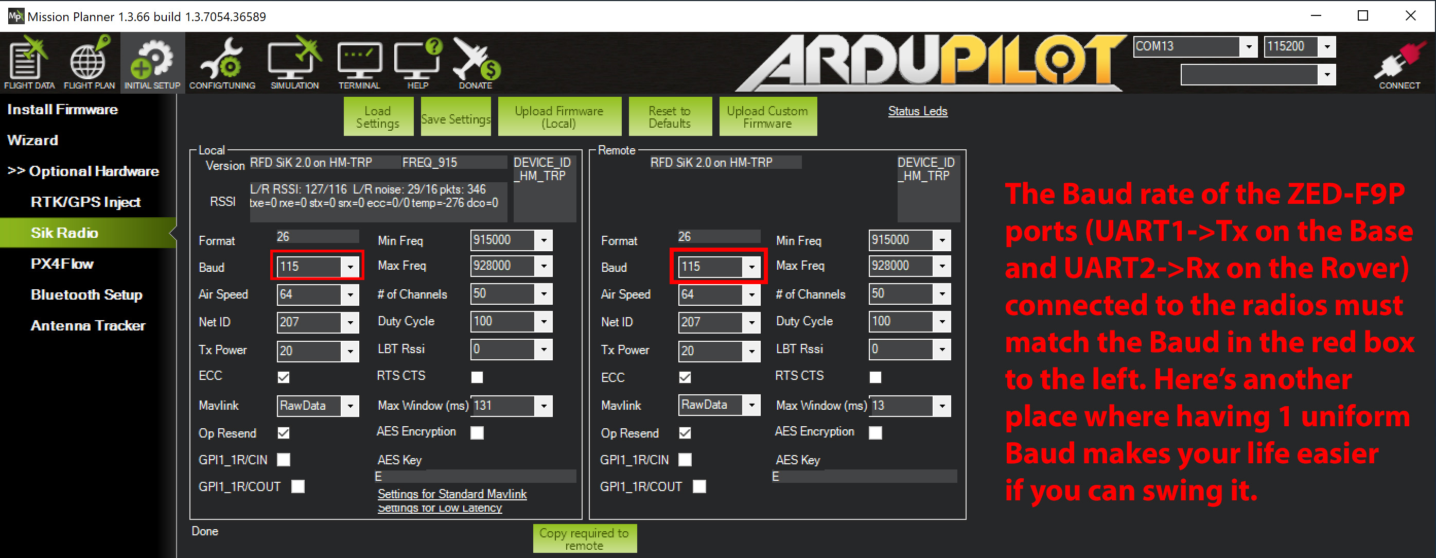
Mission Planner has built-in functionality to configure the radios.
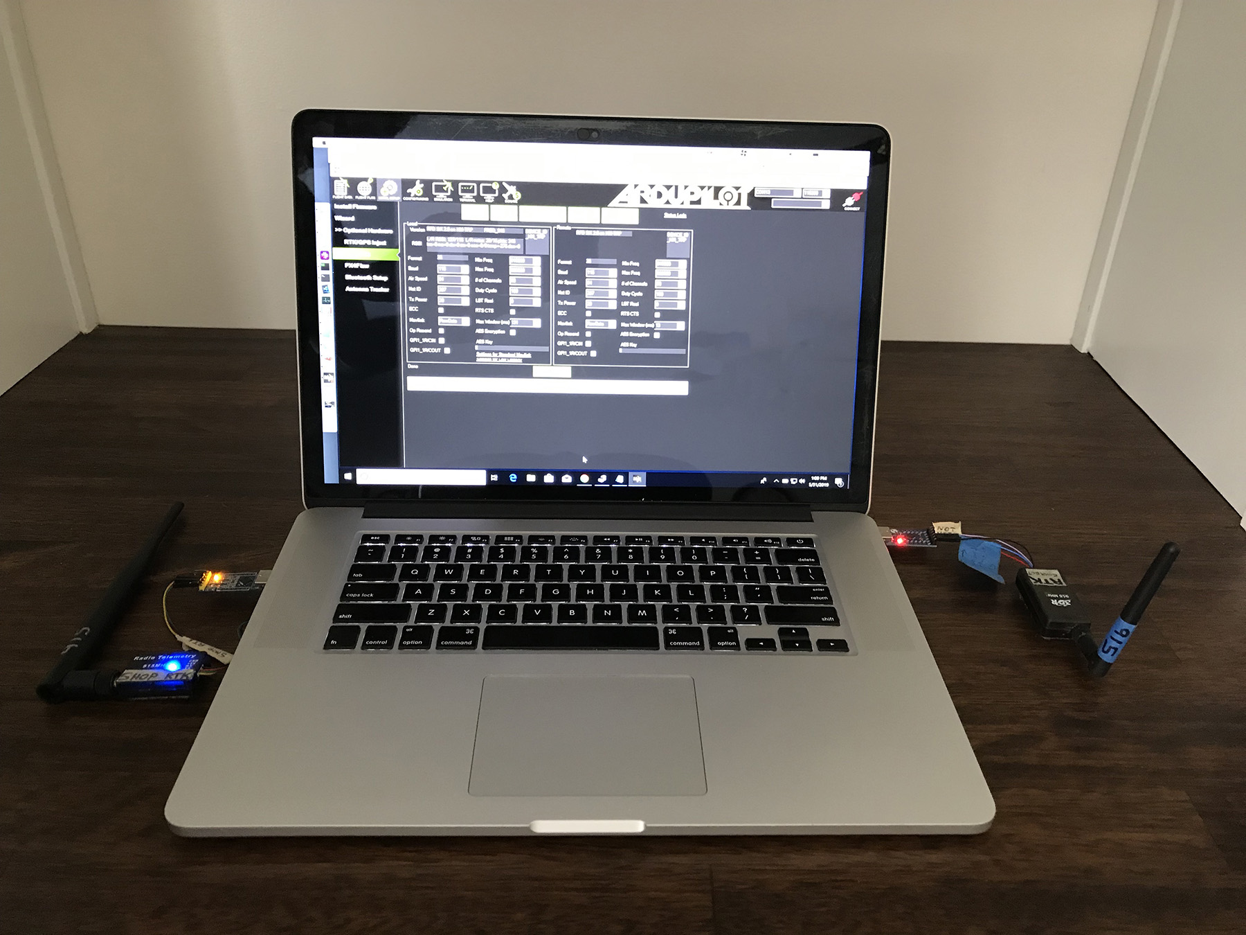
Here’s a close-up of the relevant screen in Mission Planner, along with the settings of the radios that I’m using for the link:
Now that the radios are communicating, it’s time to remove the RTCM wire connecting the ZED-F9Ps to each-other and instead connect them wirelessly via the radios.
That’s all there is to it! Note the solid yellow light on the Rover indicates it has an RTK fix — I love seeing that light.
Sincerely yours,
Roby
Footnotes
- Tomoji really is the proverbial giant on whose shoulders many stand and see far. If you’re not familiar with him (i.e. you’re new to low-cost RTK GNSS), he wrote an ENTIRE OPEN-SOURCE RTK LIBRARY (humbly and simply called RTKLIB) that’s historically significant as it enabled the first forays of hobbyists with low-cost (i.e. < 100USD) u-blox GNSS receivers (such as the NEO-M8T) into the previously exclusive world of RTK. Tomoji actively keeps a predictably low-key blog of his research notes, which is approachable to non-Japanese audiences via the Google Translate extension in your fav browser.
- Clive possesses a savant-level command of several technical spheres. Fortunately for us, he decided years ago to begin ascending the RTK mountain — he has pointed many aspiring GNSS journeymen toward the correct path.
- Tim had two important realizations in early 2016: 1. the significance of RTKLIB (i.e. the world it opened up by processing raw data output from low-cost u-blox receivers) and 2. the difficulty that non-gnss-professionals were having approaching RTKLIB. His tremendous blog has revealed the ways of Tomoji to mortal man. Additionally he has become a trusted voice (through actual field use) critiquing the various RTK GNSS offerings appearing over the past few years.
- To be fair to this (first) version of the C099-F9P — the C94-M8P development kit went through a few releases before arriving at the final refined product.
- The M8P will always occupy a special place in my heart as it signaled to thousands of makers hoping for robust afforable RTK that u-blox was getting ready to play.
Addendum 1: Finding Latitude/Longitude/Elevation for your local Base Station Antenna
The absolute accuracy of your rover’s position is directly tied to the accuracy of the longitude/latitude/elevation that you provide to your base station as it’s antenna’s location. In order to find out the longitude/latitude/elevation of your base station antenna, you’ve got several options, including:
- Rough guess by using a site like this: https://www.maps.ie/coordinates.html
- Pipe in corrections from some RTCM correction source you have access to into your Rover C099-F9P (i.e. with your Rover C099-F9P hooked up to the base station antenna) and, assuming you get an RTK Fix, note the Lat / Long / Altitude in u-center.
- On the ZED-F9P that’s hooked up to the base station antenna, run the u-blox Survey In procedure (the u-blox C099-F9P GitHub folder has instructions for running Survey In, but I couldn’t ever get it to seem to work).
- Pay a professional surveyor to survey your base station antenna location.
If options 2 through 4 in the list above don’t make immediate sense, just grab the approximate longitude / latitude / elevation via the website (or any similar website) in #1, i.e.:
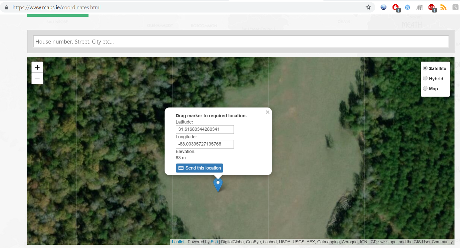
So, as an example, assuming that the map location above is zoomed in on your base station antenna, you would just pull the coordinates provided:
Latitude: 31.61680344280341
Longitude: -88.00395727135766
Elevation: 66m* (I’m not sure how accurate the website’s elevation is, but you will want to remember to add the height that your antenna is above ground to this number).
96 Responses
This is great. Im going to order my two units this week.
Have to sell some robot parts to buy these.
Its a never ending cycle.
John — You are correct my friend!
If doing integration work consider the ArduSimple shield solutions. Doing some interesting experiments with those including double-stacking them to get real time orientation with dual antenna rover configurations. ie One resolving location, the second resolving a NED vector using moving-base mode.
Thanks Clive! ArduSimple is on a tear lately — I’m itching to pick up the new heading board once it’s out.
So are you running two sets of radios? one for mission planner to the robot. and another set for the GPS corrections base to the rover?
Hey John that is right — that second pair of 3DR radios connects Pixhawk telemetry to Mission Planner.
Usually, however, that radio connection to the robot is just a backup — I prefer to use the Raspberry Pi running mavproxy and sending the telemetry to my Mission Planner via UDP. So having the on-board Ubiquiti Access Point is nice in this situation.
To be clear, here’s what that looks like: from the pictures on the previous blog post, you’ll see a USB-TTL-UART connector plugged in to Raspberry Pi’s USB. The Tx/Rx wires connect to the Pixhawk 4 Telem1 port.
You run a command like this on the Raspberry Pi to forward the telemetry to your in-network Mission Planner:
mavproxy.py --master=/dev/ttyUSB0,921600 --out my-pc-name-or-IP:14500And then from Mission Planner on your PC, you just connect to UDP:14500 and you’ve got a lot faster connection (921k baud) than the 3DR radios will usually give you.
Hey Roby,
Excellent write-up. Really appreciate your blazing the trail on the ZED-F9P.
Can I ask, how did you overlay the antenna’s path with the map of your property?
Is this the map view in u-center? If so, did you purchase a google maps API key, or create a calibrated, static image?
Hi Conner,
Thx for your kinds words! Hey that is all within u-center — I have a Google Maps API key and it was free (you do have to sign up for it though).
–Roby
Hi Roby,
Thanks for the info. I didn’t push too hard on through the Google API setup. I figured there were additional costs, but I’ll go back and play with it. That overlay is slick!
For your future readers, I did succeed in getting the ODIN modules to talk to each other on the C099-F9P dev kit, and achieve a wireless RTK fix using only 2x dev kits.
My dev kits (C099-F9P-2, purchased from Digikey) came setup for Mbed. I believe all US kits run the Mbed OS 3 application firmware from the factory. You’ll know if the kit is setup for Mbed if upon opening the port in s-center, all you see is “+++”. The ODIN-W2 modules can be setup to use the Connectivity Software / wifi using AT commands, which is what we want for RTK over wifi. After your #3 step above, I downloaded the latest version of UBlox s-center (4.8.0). You really have to carefully parse the UBlox documentation to figure out the setup. Refer to pg30 of the C099-F9P-AppBoard-ODIN-W2-CSW_UserGuide_(UBX-18055649-R04), section 7.2 ODIN-W2 Firmware Update.
To get the Connectivity Software to run you have to first flash an updated bootloader to the ODIN module. (I was pulling my hair out at this point). But before you can flash anything, you have to restart the ODIN module into safe boot mode.
– Hook up a jumper across the safe boot pins on the board (see pg 11, Figure 6: Switches and LEDs) and press the safe boot button to restart the board (or maybe its the normal reset button, can’t recall exactly).
– Flashing requires you to download a separate program, stm32flash (https://sourceforge.net/projects/stm32flash/files/, stm32flash v0.5) to a windows PC.
– Download the bootloader (ODIN-W2-BOOT-v0.8.2.bin) and connectivity software (ODIN-W26X-SW-7.0.0-090.bin) files from the ODIN-W2 product page documentation tab (https://www.u-blox.com/en/product/odin-w2-series#tab-documentation-resources) – Look under the bold heading “Firmware Update” and download the “u-blox Connectivity Software 7.0.0 for ODIN-W2” zip file. It includes the bootloader and software file. Place stm32flash and the two files in the same folder for ease of access.
– Connect one dev kit to your computer via the including usb cable. Following pg30 of the user guide, open Power Shell / Command Prompt in Windows, navigate to your chosen folder, and run stm32flash.
– To flash the new bootloader, type (replacing port number with the ODIN-W2 dedicated port number):
stm32flash.exe -b 115200 -w ODIN-W2-BOOT-v0.8.2.bin -S 0x8000000 COM
– To flash the new firmware, type (replacing port number with the ODIN-W2 dedicated port number):
stm32flash.exe -b 115200 -w ODIN-W26X-SW-7.0.0-090.bin -S 0x8010000 COM
– If it gives you errors, make sure your Baud rate, port number, and file name are exactly correct.
– At this point, remove the safe boot jumper and restart the board in normal mode.
– Open s-center (ODIN will use 115200 baud rate at this point). Open port.
– Turn off flow control by pressing the button labeled “EVK-ODIN-W2 via ST-LINK” (I believe this is required to see the AT commands, could be wrong)
– Execute these 3 AT commands:
• AT+UMRS=460800,2,8,1,1,0
• AT&W
• AT+CPWROFF
– Close port and reopen using 460800 baud rate.
– Hit the AT mode button and you should start to see AT commands per pg 31.
– Repeat the above steps for the 2nd dev kit.
– Now that you have the ODIN running the connectivity software, you can download the rover/base config files (located on the github) to the ODIN module
The last thing you have to do is hook up a jumper across the “3OE” pins, per pg 17, to connect the ODIN-W2 and ZED-F9P serial ports, and allow RTK corrections communication between rover and base.
Hope this helps someone else out there struggling!
Thanks
Conner — this is wonderful — thanks for taking the time to log the success path for getting the ODIN-W2 radio communication working.
I’m interested to learn the range of those radios.
–Roby
Hi Conner, I’m from Argentina, can you help me set up my F9P? bluetooth function .thanks
Hi Conner – your procedure worked very well and allowed me to establish a BT connection with the ODIN. So far, I have been unable to receive GGA messages through the BT link, even after following the uBlox documentation very closely several times over. I placed the jumper, downloaded configuration files, etc with no luck.
Do you have any suggestions on how to receive the NMEA-GGA sentences over BT so they can be used with NTRIP?
Thank you.
can this be use for land surveying? if does, what app to use to display survey result and point survey?
Hi Conner,
Thank you very much for your post. It was very helpful and pointed me in the right direction. Simply knowing which of the two C099 manuals to look at was a godsend. I managed to get the base and rover working correctly but not until I followed the instructions at ‘6 Reference station and rover pairing’. I am assuming you did this also? Did you notice that the arrow on Figure 6 that is meant to point to the safeboot pins is actually pointing to the set of pins below the correct ones? This had me stumped for over an hour until I guessed the docs might be wrong. Again thank you to Roby and you for paving the way for guys like me.
Hi! I would like to ask about the patch antenna used. Is there any documentation or idea where the phase center of L1 and L2 signals? Additionally, are there any options or accessories that I can put the patch antenna to the tripod (usually used in surveying or RTK) so it will be placed vertically above the point/station? thanks!
Hi Martin,
Here is a screengrab from the official ANN-MB documentation detailing the antenna phase centers:
Re: Mounting the antenna on a tripod — curiously, note that the ANN-MB antenna pictures on the official u-blox page have a through-hole flanking either side of the antenna, but the ANN-MB antenna I received doesn’t have that.
Hope that helps,
Roby
Thanks for the response. Another question is, can I use a smartphone instead of a laptop to control the device? If any, is there any application that could control the device? Thanks Roby
Martin
Hi Martin — Can you give a little more color on what you’re trying to achieve?
The C099 Dev Board contains the ZED-F9P and an ODIN-W2 module (Wifi+BT). You can pair an Android smartphone to the using bluetooth and stream RTCM data to it using an app like NTRIP Client (by Lefebure). You will need to “point” the app to your RTCM correction server with your login details.
But having a second C099 board (base station) creating RTCM correction data(as in this post) opens up many more possibilities and puts you in control.
Hi Roby, I tried logging data using DF receiver (zed-f9p) and then recorded its log data using ucenter. However, when I tried to plot the .ubx file using RTKPLOT, it says that “no solution”. As I tried to convert the .ubx file to RINEX format, nothing happens. Is there missing points or configurations I did before recording? Thanks
(you can also email me)
Hi Martin — Apologies but I don’t think I’ve ever really done the scenario you’re describing.
–Roby
Did you enable RAWX messages, and disable all others? This works well for me.
Got it! thanks
Hello.Roby!
Good to see your rtk tutorial.
Would you let me know if this is possible.
As your tutorial, with two C099-F9P board, getting cm level accuracy rtk
signal and send it to smartphone map app via bluetooth or usb connecting.
Because I want to record the gps track with smartphone app when I’m doing outdoor activity.
Have a good day. 🙂
Hi Jason that should be very doable.
Cheers,
Roby
Hi Roby,
Great tutorial! I just got my hands on a SimpleRTKB + SimpleRTKBLite with hopes of putting them into a moving-base configuration (total rookie here). Have you come across any resources on how that may be accomplished? Further how might I send position + heading information obtained to an arduino board?
Thanks for the help!
Jason M
Hi Jason,
Thanks for stopping by — I haven’t used the ZED-F9P for heading — I’ll often still use an old (and discontinued) HMC5883 here at the shop. I did see that u-blox dropped a new pdf last week regarding using the ZED in moving-base — here’s a link to the info page (scroll down to Application Note –> ZED-F9P moving base applications) where you can download it if you haven’t see this yet. It’s pretty standard to use I²C for compass communication — but depending on your needs you may choose something else.
Hope to hear you have much success with the SimpleRTKB board!
–Roby
Hi Jason,
Were you able to perform in moving base setup? I couldn’t bring it to Fix Mode: TIME.
Hi Roby,
Thanks for sharing, this has been very helpful! I am trying to do a similar setup. I have been searching all over trying to gather all the info for this on the internet. I have 2 of the Ardusimple SimpleRTK2B with XBee LR radios for correction. My Pixhawk 4 and other goodies have just shipped! I would like to collaborate more on this. For now I’ll just try to catch up.
I noticed you are sending NMEA to Pixhawk. The sparkfun website says the resolution for NMEA string does not fully utilize the precision these guys are capable of. It says the 5th digit is about 1.5cm. Did you keep this setting? Can Pixhawk 4 take the higher resolution UBX strings or can you increase the resolution of the NMEA strings?
Thanks,
Mike
Hi Mike,
For the Pixhawk 4, I’ve only run ArduPilot accepting NMEA and its works fine (you’re not going to want that baud rate any lower than 115k though — maybe higher if you’re going over 5Hz PVT with the ZED). By now ArduPilot may have ZED-F9P UBX working on the u-blox driver, but since NMEA works fine I just haven’t checked. Also, that 1.5 cm figure you saw for NMEA precision sounds about right. I remember a few years back there may have been a little funniness within the ArduPilot code about cm-level waypoints, but for a good while now it’s seemed quite solid to me. Now if you’re wanting to get down to millimeter accuracy, you’re playing a game with which I’m not familiar.
Look forward to hearing about your build!
–Roby
Hi Roby
Thank you so much for your tutorial. I’m so glad I found your blog. I live in the northern part of Denmark, where I try to get knowledge about the gnss/rtk technology. Im running a similar setup with two Sparkfun RTK2 kits. I was able to reproduce your setup and read the rtcm signal from the base, however I had problems reproducing it later in the day, when I tried to use I2C. As for now it works when I send the signal from base Uart1-tx to rover UART2-rx (460800 Baud). But If I use base UART2-tx to rover UART2-rx, the signal disaperes after approx. 1 minute. Somewhere in your videos you mentioned that you had done some tweaking on these matters, is it possible that you could share your experience?
As a side note I should mention that my antennas at the moment are poorly located very close to my house (Should have bought longer SMA cables?) , but I dont see why that should produce any difference between the UART ports.
Thank you in advance and have a nice day.
Morten Westeraa
Hi Morten!
Warm greetings to you across the pond in northern Denmark.
Glad to see you figured out the issue shortly after posting this (i.e. starting with the base config files from GitHub). For some reason, on the rovers I’ve ended up going with sending in RTCM on UART2 Rx and outputting PVT on UART1 Tx — I was having trouble, for instance, getting PVT to output on UART2 Tx but that may have been something I was doing wrong — in other words, I stumbled into that UART1 PVT Tx / UART 2 RTCM Rx configuration and it worked so we just stuck with it :).
If you’re building a rover, hope to see some pictures of it running around your beautiful country before long!
Take care,
Roby
I forgot to mention that I use the hardwire connection as for now, sorry?
I found out why it would not accept correction signals from base UART2 tx. They were not set up in the base config file from Github. After changing this file I now send RTCM from base UART2 tx to rover UART2 rx, at 460800. The update rate is 10 Hz.
Hi, I can successfully configure a moving base setup at 5Hz but if I also try to send RTCM corrections to the reference module from the local CORS site in order to get both an RTK position as well as heading, then the corrections from the reference receiver to the attitude receiver periodically stop causing frequent ‘zero heading’ output from the heading field of the RELPOSNED message from the attitude receiver (along with a corresponding accuracy of 180 deg). Corrections between the reference receiver and the attitude receiver are on uart2 at 460800 baud. Corrections from the CORS station and the reference station are on uart1 at 115200 baud. All unused messages are disabled on all ports. Is this setup supported by the F9P? I have made changes to Ardurover to accommodate this setup and can successfully use the heading in EKF3 and obtain accurate headings without using any compass but the frequent dropouts causes issues…
Hi Jimovonz,
Apologies but I haven’t used moving-base on the ZED-F9P.
I’m hoping that a near-future iteration of the ZED will natively support 2+ antennas on 1 board (thus enabling absolute pose data) — considering that u-blox has already superseded the F9P with the ZED-F9K (with IMU onboard to fill in temporary GPS “gaps”), it seems reasonable to conclude that u-blox is planning on quickly pushing through the feature-enhancement roadmap that the big expensive old-school GNSS companies did with their multi-thousand $$$ USD receivers.
If you do figure out the quirk you’re seeing, I hope you’ll consider reporting your findings.
Take care,
Roby
Hi Roby,
very great and detailed article about the F9P.
I have also purchased the F9P, i have one small question, can you please provide your valuable feedback?
-> I have configured the F9P over USB port(UBX-CFG-PRT) on the raspberry-Pi with UBX+NMEA+RTCM3 for protocol-IN and Protocol-OUT. For the NTRIP client configurations, how can i configure it over the USB port from raspberry-pi ? can you please point out to any rtklib or
Hi Roby — I purchased a ZED-F9P Dev board — c099.
My primary goal is to use it for static observations and correct using OPUS or similar service. It has been 3 weeks and I have yet to produce a .OBS file (converted from .UBX using RTKCONV)that has been acceptable to OPUS.
I have received several error messages from the OPUS system that indicate that the unit may be in kinematic mode. Any config suggestions? I am collecting the data using SW Maps running on an android.
As a separate issue, I have had no success using the built in bluetooth radio — i can connect but i have no GNSS stream.
Thanks,
Mike
Hi Mike,
Glad you stopped by.
I don’t have any experience with any kind of surveying application — but you may find some help over at https://rtklibexplorer.wordpress.com/.
In the comments above, Conner gave the steps he followed to get the radios communicating — I haven’t tried these (after failing to figure out the radio config earlier) since I’d rather just use a cheap 3dr radio with great range.
Take care,
Roby
p.s. For future readers, ArduSimple has got enough traction at this point that buying their board may be the path of least headache to getting what you want out of your F9P.
Hi Robo,
I’m a newbie. I just got started with the kit. I want to connect my f9p and get the lat long coordinates on the Android app that I’m created. I checked out for the same but couldn’t find any luck though. Can you please suggest me on this.
Thanks
Chandu
Hi Chandu,
Glad you stopped by.
I suppose you could pipe the data from the C099 USB port to your Android’s USB port — but I’ve never done this with an Android. Also, I’ve got no experience using the Bluetooth/WiFi functionality on the C099 board.
If you do end up rolling a solution, I hope you’ll consider pinging back here how you pulled it off.
Take care,
Roby
Dear Roby,
This video has been fairly informative for me and I am thankful to you for the same. However I am very new to all of this, and hence, I had a couple of questions. Upon your advice I have purchased 2 of these boards. ANd I am now trying to get them configured in base and rover configuration
Why did you not use an NTRIP client? Is this because you are giving the position of your antenna to be fixed?
In my case I would like to use an RTCM stream over NTRIP. Despite indepth reading online, I am still facing some ambiguity in terms of the base and rover configuration. This goes with the NTRIP Caster and NTRIP client part. From my understanding, the base will act as the NTRIP caster, and the rover will act as the client? I intend to keep the base connected by USB to a laptop that will have active internet connection. I intend to also use an NTRIP stream provided locally by TU Delft here in The Netherlands. Please correct my understanding if I am wrong. In this case, I’ve been asked for a username and password which I do not have but only have access to the source table. So it’s a little bit confusing.
Secondly I want to ask exactly why you don’t use the built in ODIN radio on the board itself ? It is because of range limitations ? Is this becuase of range limitations ? I would be having an operating range of say roughly 100 meters, and I assume I should be able to use the built in ODIN radio ? Kindly advice me in this regard.
Thank you
Hi Shrivaas,
Our setup doesn’t need an NTRIP client because our cheap SiK telemetry radios (i.e. 3DR radios) take care of sending the RTCM corrections from the base station to the rover.
So, just to be clear — if you have 2 ZED-F9P boards, you have everything you need for your RTK setup. You don’t need any other correction provider, and you don’t need an internet connection unless you’re needing that internet connection for something else (like, say if you’re wanting to send the corrections over the internet instead of using a telemetry radio [or the onboard radio]).
Speaking of the Bluetooth/Wifi radio onboard the C099 dev board, I don’t use that radio for the very noble reason that I tried using it and it was difficult, so I just use the easy/cheap SiK telemetry radios. There are a few folks in the comments above who have apparently had some degree of success with those radios.
Best wishes,
Roby
I’ve been watching this space for quite some time, as I’ve been working for the last couple of years on a very similar project, using an C94-M8P and an Intel RealSense D435 to build an autonomous mower that discovers and mows without border wires. I’m currently not far from where you are, currently tinkering to get an IMU which provides reliable yaw. FWIW, here’s a review of the C94-M8P https://www.calvert.ch/maurice/2017/08/28/ublox-c94-m8p-rtk-gps-review-performance-evaluation.
Hopefully I’ll have something to show this spring >;-)
Best regards,
Maurice
Hi Maurice,
Your blog is a tremendous source of engineering information. I especially appreciate your post (and GitHub repo) about increasing the performance of the RealSense D435: https://www.calvert.ch/maurice/improving-the-depth-map-accuracy-of-realsense-cameras-by-an-order-of-magnitude/.
Take care,
Roby
Hello Roby,
Thanks for the video. It was the nudge I needed to say “I can do this” It was a lot of work, while frustrating at times, it was fun and very rewarding.
I am now running on the Indiana CORS network with a Ntrip client feeding the F9P via ODIN Bluetooth. I was so satisfied to see the RTK float come up. Simply going outside and getting more satellites brought up a fixed position. I have made some notes as I went. I kind of want to try it again from opening the box to see if it would be much easier starting over. I generally get it to work once, and then go through setup a second time making notes. But I am not sure I needed to do all that I did. IE firmware updates and such.
I did have a lot of trouble getting the PC to connect. The USB hub on the board needed to be run on WINDOWS 10. Windows 7 PRO couldn’t handle it properly, s-center would not talk to ODIN. U center was no problem.
Any way, my next step it to switch from USB cable to one of the Uarts and get that into the PC via serial port. I am going to run this into tractor guidance, and being enclosed will prevent easy access to the board. I have extra pins in the cable for this, so that is the plan.
Again Thanks for the courage to share, and allowing me to get this working.
Hi Andy,
Glad to hear you’re rolling — hope to hear about your tractor guidance integration once that’s going too.
Take care,
Roby
Roby,
I’m assembling the ZED into box that will reside on the tractor. One thing that came up in discussions with other farmers was newer RTK GPS have an algorithm that when the RTCM data is lost after it had a good fix the GPS will continue to use the stale RTCM for up to 20 minutes. This prevents the tractor to revert to WASS which we know is way off line. Does the ZED do this automatically? I see no mention of it in features, or is it just assumed to have it. If not, I am considering adding an arduino to do that. I would think that your projects would need to be protected in similar situations.
Thanks Andy
Hi Andy,
It seems like the ZED will go for ~1 minute with an RTK Fix after RTCM messages stop. It does seem like I may have heard that this setting is configurable, but I’m not sure about that.
Take Care,
Roby
Was wondering how your project is progressing. I am running agribus navi with a garmin glo. After two times applying fertilizer with this setup I realize I need something better. Been reading a lot about the ublox, and think I want to dabble. Any suggestions.
Hello Mr.Roby,
Your tutorial was very useful in understanding how to setup the ZED F9P module.
I am using the Sparkfun Gps RTK2 board that houses the same ublox module, following all your steps i am unable to set the base station to TIME mode. I tried both survey in mode as well as fixed mode entering my approximate ECEF co-ordinates but Ucenter only displays a 3D fix.
I also tried using an rtcm base Arduino code from the Sparkfun ublox library, Although i am able to get it to transmit the rtcm corrections, my rover does not receive the RTCM 1005 message and therefore does not provide rtk corrections. I have been struggling with this for quite a while and it would be very helpful if you could give me an idea on how to obtain rtk corrections from this development board. Thank you for your time and consideration.
Regards,
Rohith
Hi Rohith,
First thought is to make sure the baud rate on the Tx port of your base station is the same as the baud rate of the Rx port on your rover.
Make sure the Tx port actually is sending RTCM messages.
Make sure the Rx port on your rover is configured to receive RTCM input.
The longer you play around with u-center, the more it’ll all start to make sense.
Take care,
Roby
Excellent write-up!
I recently picked-up a pair of the Emlid RS2 units and they are pretty good. I believe they are F9P-based.
Emlid also just released the M2 modular kit and it looks like Spark-Fun also has a board available now for the makers.
Especially with RTK-Lib available for the PPK market, it is interesting times.
Hi Matt,
Do you have a feel if Emlid RS2 is making inroads into the professional surveying community?
Take care,
Roby
They are definitely displacing Trimble gear in mapping markets (especially Archeology), agriculture mapping workflows and drone mapping markets.
They are not yet getting full buy-in from the RPLS community as far as I can see. For a few reasons..
1) NSG Antenna calibration parameters.. alot of people asking for this and it is ‘in-progress’ for the last year. I think it has to do with Post-Processed workflow and OPUS / NRCAN-PPP, etc..
2) Intermittent OPUS processing issues for some reason, again, I think this is due to the lack of legacy L2.. likely on the OPUS side to improve compatibility.
I bought 2 UBLOX ZED-F9p boards from SparkFun and without too much trouble set them up using XBee radios to communicate between the Base and Rover. Long story short is everything works really well with worst case accuracy of about 1.5CM.
Now I need help the F9p Rover with PixHawk 4. I see you’ve done that but I can’t find any details on how you did it.
Hi Nielo,
Glad to hear you’re having success with the ZED-F9P.
I’m using a Pixhawk 4 with the F9P on a big mower and wrote up the details here. Note the param file at the bottom of that post.
Take care,
Roby
Thanks for the info, it will give me something to read 🙂
Hopefully it will have some description on how to hook the F9p to the Pixhawk 4 electrically and to configure the F9p/Pixhawk so they can talk to each other.
Hello Roby,
I am building a ground rover. I want to use ZED-f9P as my gps unit and i want to know how to configure it. What all do i need? I have replaced the here gps module with the F9P. Now what do i need to establish a connection with it and the pixhawk 2.1? The RTK tab seems to have been configured and it says result is fix but my HUD says no GPS. The f9P is connected to the PC and the Pixhawk is also conected to the PC as of now. What do i need to do on MissionPlanner? I am a beginner and have no idea, so please help.
Hi Nielo
I have also bought two Sparkfun RTK2 receivers, and managed to get a good RTK fix with my setup of moving base and rover, using a wired connection. I have been unable to establish a wireless connection; I first tried a pair of basic ESP8266 wifi modules, then a pair of WemosD1R2 modules without success. I have just bought a pair of Xbee 3 modules, and still struggling. Could you explain how you configured your Xbee’s to send the RTCM messages?
Richard
Hi Richard,
I’m using wonderfully-cheap-and-long-range 3DR radios. Details on radio setup toward the end of this post: The Taming of the u-blox ZED-F9P.
Sky Horse Tech has a recent post detailing a setup with 3DR radios with Sparkfun GPS-RTK2 receivers.
Take care,
Roby
I have a configuration problem with the outgoing UART1 and UART2 serial ports. I use this configuration:
01 10730004 CFG-UART1INPROT-RTCM3X
01 10740001 CFG-UART1OUTPROT-UBX
00 10740002 CFG-UART1OUTPROT-NMEA
00 10740004 CFG-UART1OUTPROT-RTCM3X
01 10750001 CFG-UART2INPROT-UBX
01 10750002 CFG-UART2INPROT-NMEA
01 10750004 CFG-UART2INPROT-RTCM3X
00 10760001 CFG-UART2OUTPROT-UBX
but instead of leaving UBX or RCM3, NMEA always exits from both UARTs (by setting on UART1 UBX + NMEA + RTCM3 as input and UBX as output, only NMEA messages and on UART2 UBX + NMEA + RTCM3 as input and RTCM3 as output, only messages NMEA)
I have the latest firmware installed.
My software version is EXT CORE 1.00 (61b2dd) and my firmware version is 1.12
Can someone help me?
Hi Marco — I don’t know what’s up with this — prob hit the u-blox forums?
Take care,
Roby
Hi Roby
Thanks for your recommendation to use 3DR radios, they seem out of stock here in Australia. In the meantime I will battle on with my Xbee’s as they are smaller, which is important for my application.
Richard
My Xbee problem was solved by simply connecting the Xbee’s directly to the F9P GPS module, instead of via the Xbee Explorer USB adaptor! I don’t understand this, but now my two F9P receivers now run in FIXED mode with a wireless connection. My next challenge is to process the rover’s RELPOSNED message on my Pi to drive pan and tilt motors; this should keep me busy till the end of lockdown.
Hi Richard,
Glad you figured out the problem!
Take care,
Roby
Has anybody used python to extract relative heading and tilt from the rover’s UBX-NAV-RELPOSNED messages? Are there easier messages/methods to get real time access to this data for guidance applications?
No experience with this from me 🙁
Its been a while since the initial posting so I have a couple of questions.
1. Does the C099-F9P dev kit contain the actual GPS unit?
2. Since your initial article was in 2019 are your current recommendations the same or are there newer versions of the dev kit or GPS units that have come out since then? I would assume the dev kit has the latest version to the GPS unit but wanted to be sure before I purchased.
-Thanks
Hi David,
1. Yes. The ZED-F9P L1/L2 GNSS chip is embedded in the C099-F9P board.
2. The big innovations in the 11 months since this article are 1. the new iterations of F9 chips that u-blox is pumping out geared at specific industries, and 2. several solid boards using the ZED-F9P chip for you to choose from based on your needs/tastes.
Either the official Dev Kit or the ArduSimple boards should be a great choice.
Take care,
Roby
Hi Roby,
Great article! Very helpful. I am planing on buying ArduSimple simpleRTK2B. Can I use the same configuration files for rover and base from https://github.com/u-blox/ublox-C099_F9P-uCS/tree/master/zed-f9p used on C099-F9P board?
Can you give us some details on sending the RTK correction signal to rover via Internet. Since I’ll be using GNSS in agriculture, I’m planning on sending correction signal with rtk2go. What do I need to send the signal from base to rover?
Hi Teo,
1. I think you should be able to use the same config files since both the ArduSimple board and the C099-F9P board both have the ZED-F9P chip.
2. Will be interested to hear your experience with rtk2go — haven’t used that but do like the idea of a central service aggregating volunteer’s base station feeds — it feels like a rough corollary to open source software.
3. Here’s a repo with some python scripts I use for pulling RTCM messages from some server and relaying the messages out to my rovers: https://github.com/waynebaswell/rtk-scripts. Note this script in particular: https://github.com/waynebaswell/rtk-scripts/blob/master/write_ip_rtcm_to_serial.py will pull RTCM messages from an RTCM server and push them to the serial port you specify. If you don’t know the name of your the local serial device you want to talk to, here’s a script that should give you a hint: https://github.com/waynebaswell/rtk-scripts/blob/master/list_attached_serial_devices.py
Take care,
Roby
Roby,
I’m trying to get somewhere between mapping grade and survey grade GPS on a budget. Most places point to the u-blox, but you’re one of the few people to write about it (please make more blogs/videos). I know my use case is a bit different, but I’m hoping you could give me your thoughts. My primary goal is locating some property markers in a densely wooded area. I’d also like to mark some trails and creeks on my property. Being off by 25+ feet gives me a big area to search, and/or some pretty inaccurate trails. Being off by a foot or so would probably be acceptable.
I think I can use a single C099-F9P board to send (via bluetooth probably, not clear on this part) data to my phone (mock location on Android). For my base station, rather than a second F9P, there is an CORS station about 20km/12 miles from me I can use via NTRIP (3g). This is a little farther out than ideal, but I’m also not looking for 1cm accuracy. I can use an app like NTKGPS+ or NTRIP Client as my mock location app. The phone will have it’s own power, and I can power the C099-F9P with a standard USB power pack.
I’m looking at the C099 over some other products since it seems to come with everything needed (mostly looking at the Bluetooth and antenna). Ardusimple is ~$10 more and still needs a Bluetooth module, Sparkfun is ~$30 cheaper, but needs both the antenna and Bluetooth. However, the price is close enough on all three, that I’d rather just go with whichever is easiest to setup.
My biggest concern here is forgoing the recommended second F9P and using a CORS feed. I don’t know if this will work for a real time accurate feed, or what kind of accurate I will get. I know this is a different setup than what you have used, but I would appreciate any feedback, or guesses on if it will work and/or how accurate it will be before I spend good money. I’d love to just try it out myself, but I would hate to get halfway down the road and find out my plan won’t work (or the costs will be double my expectation).
Thanks
Hi Mike,
Here’s the thing, if time is money for ya’ then I’m not sure you want to try to decipher however you’re supposed to communicate with that u-blox bluetooth radio. I lost several hours in a similar endeavor last year and am none the wiser for having tried. I’m convinced u-blox had a bunch of old bluetooth/wifi chips sitting around that they needed some use for and hence they mated the industry-shatteringly-awesome ZED-F9P chip with a lamentable-range radio.
To your situation — you should be able to get what you need out of the ZED-F9P if you have a solid source of corrections at 20km and a good ground plane on your antenna. But… if you’re going to use this setup much, I think you’ll thank yourself quite often for buying your own base station.
Take care,
Roby
Thanks for the reply! I’m going to try it with a single F9P and see what I get. If I do end up using this quite a bit, I can sink more money in later. I’ll try to return and let you know what my results are and what board I ended up getting.
I don’t suppose you have a copy of u-center v18.06 still saved somewhere that you can put up? It seems like the latest (v20.01) still has the map bugs, and ublox no longer hosts anything earlier than 18.16.
Hey Mike — I checked but I don’t have that file laying around.
Hello Roby,
I highly appreciate the detailed explanations on your setups.
Could you please tell me if you’re aware of a solution integrating the official u-blox C099-F9P board with a Raspberry Pi and a smartphone (to provide NTRIP correction data) to obtain network RTK positions? This would mean not using the u-blox u-center software (Windows only) and relying on rtklib running on Raspbian.
I’ve seen similar solutions using the ZED-F9P chip on boards from different vendors (such as Ardusimple simpleRTK2B, or SparkFun GPS-RTK-SMA Breakout), but not using the official u-blox C099-F9P board.
Thank you.
Hi Bogdan — I’m not aware of this, but honestly I probably wouldn’t be aware if there were 10 good solutions for doing what you’re looking for. At some point I assume there will be some really polished interfaces out there for the ZED — right now I can just tell ya’ that it’s a great chip.
Hi Bogdan, I am trying to do the setup the same configuration using ntrip stations close to me . I do not know if you got a solution.
I used a RPI4 board, gpsd to get the ntrip rtcm3 messages redirecting them to the C099-F9P configured as base:
gpsd ntrip://foo:bar@ntrip.example.com:80/example-stream WHERE foo is the username and bar the password to access the ntrip server and example-stream is the mount point. Use the LAST version of gpsd (3.21), the previous do not understand all RTCM3 messages. Adding the /dev/ttyAMA0 (the USB port of C099-F9P ) on the command line , the manual says that gpsd send the rtcm3 messages to gps. I am trying to see if it’s correct.
Roby
Can you help us understand the difference between the internal radios in WIFI mode and the external radios you are using in relation to the distance capable between a base and rover?
Does one solution provide longer range coverage or are they about the same? If they are about the same distance-wise are there other pros and cons you can share with us to help us decide which route to go?
My ZED-F9P rover show pix mode: 3D/DGNSS/FLOAT.
How to show 3D/DGNSS/FIXED?
Roby
Can you help with which F9P to buy. Currently I am the new owner of a raspberry pi 4 and I wish to connect a F9P(not sure which one and how) to the Rpi and use as a rover collecting rtk cm accurate data. I was hoping you could shed some light on how to stream the F9P data to the Rpi and what parts where needed to complete.
I would then use the system to collect data points for hydrants, stop signs etc, point data mainly for experimenting until I get a better handle on how to use and if I need to post processing or use NTRIP on my iphone from the Rpi.
Can you shed any light, hopefully I wasn’t to confusing. Thank you for sharing your knowledge, this subject and options are a bit confusing at times.
grifway
Hi Rob. Thank you very much, your video helped me a lot in the beginning with C099-F9P. Conner’s Odin W2 upgrade instructions are amazing, but this procedure is very complicated. I wondered why someone as ingenious as the creators of C099-F9P would sell us such a device that is so difficult to use. If you haven’t solved it yet, the procedure is as follows:
1st part
-According to the Ublox video, set up one card as Bluetoth Rover using Terraterm for about 16 minutes,
-pair with a mobile phone
Launch Ntrip Client on your mobile phone
Part 2
-connect USB second cards – Base to PC
-Start U-center. In the U-center, start the NTRIP server
-Use wifi mobile phone to connect to your own NTRIP server running in U.center.
You can also connect the Base to a PC using Wifi Odin. then there is no need for a cable between the PC and the Base.
If you are on the same subnet everything is ok. If you are outside the subnet, it is necessary to set up a router to redirect you from the external Internet to the internal IP computer running the U-center with the server.
No need for a complex public Ntrip server.
No need to reinstall ODIN.
It’s so ingeniously simple and compact ZedF9P + Odin
forms a great whole.
I apologize for the machine translation into English.
Thanks
https://discuss.ardupilot.org/t/ublox-c099-f9p-integration-pixhawk-2-4-8/66050/2
Jirka CZ
Hi Roby, thanks for this great tutorial. Can you upload a closer look of the wiring between the 3dR Radio antenna and the Base Station. I’m still struggling finding the right pins to connect my 433 Mhz Radio Antenna with my C099 F9P Base Station. What happens with the TX Cable?
Hi Roby,
thank you very much for this great instruction. Can you upload a closer view of the wiring between the 3DR radio antenna and the GNSS Receiver. I’m still struggling finding the right pins to connect.
Thanks
Matthias
Hi Roby, do i have to make any changes in the MissionPlanner Configs as shown above if i want to use the Radios for communication btw Base and laptop? I did configure it similiar to your setup but connected TX and RX to the UART1 port. I can receive UBX, NMEA and RTCM Messages in U-Center but unfortunately i can’t send UBX Msg via the Radio to configure my Base wirelessly. I did check my ports and put UBX as well as input and output for UART1. I also double checked the baudrates, so i assume i have to make some changes on the radio. Can you help me out?
Thanks
Matthias
Hi Roby, thank you very much for this blog, it helped me a lot.
For anyone using ardusimple boards: there is a IOREF pin, that needs to be connected to 3.3V.
Otherwise, you can’t use the UART ports.
Manuel
thanks you saved me a lot of time!
Robby
Excelent blog!
Do you authorize me to publish in Portuguese in our site ?
Thanks so much for this hands-on crash course. Should it may help anybody in the F9P community, this is a link I posted on GrabCad this morning. It contains a self-designed 3D printed enclosure to host your EVB-C099-F9P modules (STL files). You just need a 3D printer and 6 screws. Enjoy.
https://grabcad.com/library/ublox-evb-c099-f9p-enclosure-1
I did the steps twice but when I connected the RTCM pin the rover 3D did not change to 3D/DGNSS/FIXED. Please help me with what I could be doing wrong.
You connected the rover with U center for live demonstration. Can I contact rover with Android like SW Map? if yes how can I do so. Please answer
Roby (Wayne),
Love your work ! – and thanks for the plug for Aussies’ contributions – we’ve been playing with mowers for many decades !
Quick question (I hope) – I just want good quality UTM coordinates for remote boundary surveying on my farm, and am trying to get an RTK setup going using two SparkFun Surveyor modules (Zed-FP chipset), and two Sparkfun LoRa 1 watt radios (SparkFun LoRaSerial Kit – 915MHz WRL-20029).
After about a billion iterations of parameters on U-Centre etc etc, I am finally getting an RTK fix between my PPP Base and Rover – BUT it is very intermittent – maybe 30 seconds, and then back to Single fix (Using SWMaps as my Rover GUI).
I don’t need speedy updates, just accurate, long distance (approx 1-2 km forested country), reliable coordinates.
In short, have you any experience with these radios ? and/or suggestions to “get the settings right” ?
Thanks in advance – I owe you 1,000 beers !
Best Regards,
Jeff
PS – yes I’ve tried everything !!! 🤣🤣
Hey,
I had an issue regarding the same. I am using 2 ZEDF9P for getting centimeter level accuracy. The base is directly connected to the rover via UART2, as suggested in the integration manual of ublox. I have all the necessary messages enabled on the base and rover, also given in ublox datasheet. Ucenter is even showing Fixed solution, but still after mapping those coordinates, the readings are inconsistent. Both rover and base were kept 3-4m apart in static position and the base is configured in SurveyIn mode. You may ask for any necessary information you need to know. Your help would mean a lot.
I am using simpleRTK2B starter kit for base and rover. My Base is fixed position and rover is movable. I have connected ground pin at Base to ground pin at Rover. I have connected Tx2 at Base to Rx2 at Rover by wire. I have configured Base and Rover. But i haven’t get 3D/DGNSS/Fixed.