The post last month on RTK GNSS systems continues to generate conversation both on this blog and offline. It turns out that I wasn’t the only person who entered the world of RTK without a perfect knowledge of the rules of the game.
In that post I couldn’t quit raving about the ComNav K501G card. The reason for this, of course, is that the card is awesome.
Not awesome is the temporary dearth of information explaining how to use the K501G. I say temporary, because right now we will commence building the internet’s knowledge base for working with this superb card.
The Case of the Missing Quick-Start Guide
Back in 2016 when I was on the uncharted frontiers of K501G exploration, ComNav published a quick-start guide that proved quite helpful. For some reason they no longer offer it on their site, but I found it in my archives, and am posting it here in hopes that it helps you out as well.
While we’re at it, let’s go ahead and post an archive link to the K501G v1.5 reference manual:
ComNav OEM Board Reference Manual_v1.5
And while we’re still at it, here is a link to ComNav’s canonical documents.
Using the “Dev Kit”
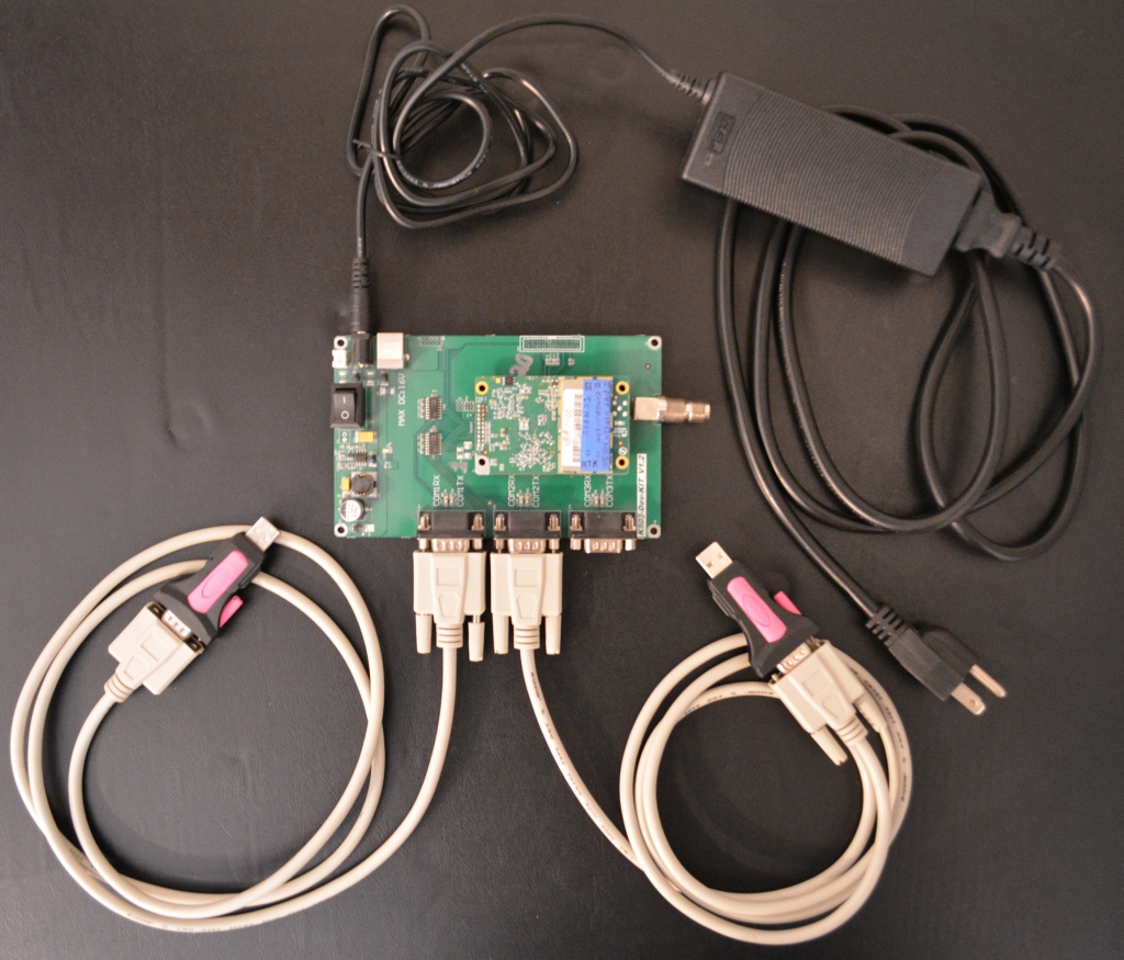
If you’ve found yourself in possession of a “dev kit” for the K501G, then you likely have a setup like the one pictured above. I forgot to include the GPS antenna cable and GPS antenna in the above picture. The GPS antenna, of course, connects to the TNC Female barrel connector on the dev board above. The dev kit is simply there to make it easier to configure and test the K501G. If you’re on a really tight budget, we’ll show below how you can get by just fine without a dev kit.
The big idea to keep in mind when working with the K501G board (other than don’t kill it with static), is that you can communicate with the board on any of it’s three I/O ports. These ports, unsurprisingly, are called COM1, COM2, COM3. Later on we will give the K501G instructions for what kind of output to write or input to accept on each of these ports.
You’ll notice in the dev kit above that the dev board uses three 9 pin RS232 connectors for connecting to COM1/COM2/COM3. I have no clue why the RS232 connectors are used (instead of, say, a straight USB connection) — perhaps it’s a joke, maybe they wanted you to think about the 90s and get nostalgic — more likely, I suppose, there’s some legacy reason why dev boards were made this way years ago and it’s now easier to ship RS232-to-USB adapters rather than design a new dev board.
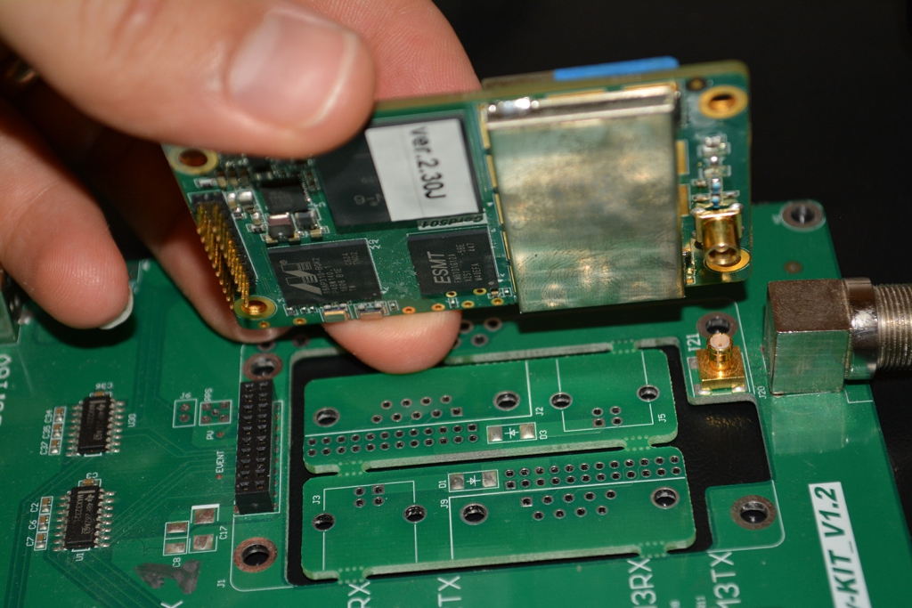
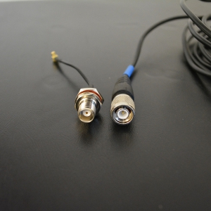
Go ahead and mount your K501G to the dev board, connect the 9 pin RS232-to-USB connectors to your dev board, connect the antenna to the dev board via a TNC-Male-to-TNC-Male antenna cable, and connect the power supply to your dev board. You’re now ready to flip the “On” switch on the dev board.
In the dev kit setup pictured above, we connect the 9 pin RS232 connectors to COM1 and COM2. You may be wondering why the board has 3 communication ports. I can’t speak for the manufacturer’s motives, but I can say that having 3 ports allows you to cleanly segregate the duties of each port.
For example, take a look at the writing on the blue tape on one of my K501G boards:
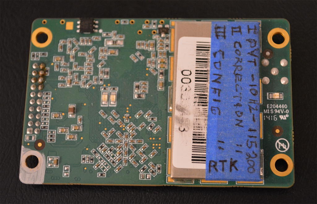
Notice on the blue tape above I’ve labeled the function of the ports as follows:
- Port 1: PVT (Position, Velocity, Time) OUTPUT
- Port 2: RTCM Correction INPUT
- Port 3: Configuration (I connect to this port to configure the board — in theory you could connect to port 1, but with 10Hz RTK output, the port will likely become congested).
If you’re going to spend much time with these boards, you may find that labelling the port’s function spares considerable future confusion.
Configuring the K501G with Compass Receiver Utility (CRU)
In order to configure the board, we’re going to use the software ComNav provides called either “Compass Receiver Utility” or “CRU OEM Board Control Software” (direct download link, download page link). Compass Receiver Utility (hereafter called CRU) is not particularly intuitive for a NON-GNSS-Professional user. I’ll attempt to give you the high points you’ll need so that you can get your board configured as either a rover accepting corrections and outputting PVT data or a base station outputting RTCM3 corrections.
For the following instructions, I’m assuming you’ve connected your Windows PC to PORT 3 via the RS232-to-USB adapter. Why port 3, you ask? No technical reason, just as a habit I like to always configure the board via port 3. We will configure port 1 and port 2 like I configure my boards (remember the port descriptions above the beautiful picture above).
Be sure that you’ve turned the dev board’s power button on – maybe it’s just me, but I’ve somehow overlooked the power button on the dev board more often than I’d like to admit.
Once you’ve downloaded and installed CRU, you’ll want to open it up.
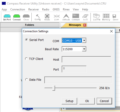
In the upper left hand corner of CRU, click the “Set Port” turquoise button. In the “Connection Settings” dialog box, select your COM port from the “COM” dropdown box. Next select the appropriate baud rate from the “Baud Rate” dropdown box. I believe the default baud rate is 115200 for the K501G. Let’s assume that baud rate is correct, now click “OK”.
It turns out that CRU is quite ambitious and once you click “Ok” it establishes a connection to the COM port you selected (no need to click the green “Connect” button in the upper-left next to the “Set Port” button).
Now let’s verify that you’re actually connected to your K501G board.
In the CRU, click the black “Command” button near the top/center. This will bring up the “Command” dialog window pictured below. You can type commands into this window and click “Send” to send them to the K501G board. Here’s the thing:
YOU MUST CLICK “ENTER” ON YOUR KEYBOARD BEFORE CLICKING THE “SEND” BUTTON.
YOU MUST CLICK “ENTER” ON YOUR KEYBOARD BEFORE CLICKING THE “SEND” BUTTON.
YOU MUST CLICK “ENTER” ON YOUR KEYBOARD BEFORE CLICKING THE “SEND” BUTTON.
If someone had just pointed that out to me (and if I had remembered it) it would have saved me hours of frustration. In programmer speak, the board does not process a command until it sees a \n (newline) character.
Let’s begin by showing the WRONG WAY to verify your connection:
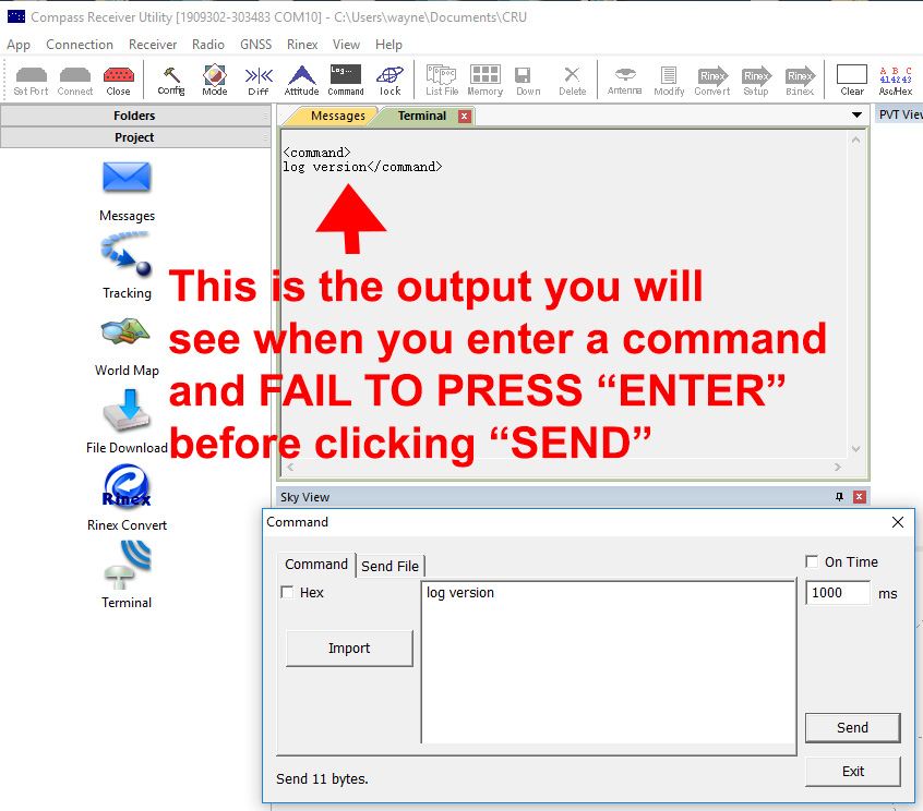
Notice in the image above that the “Terminal” tab at the top displays both the command you send to the K501G (via the Command window) and the response from the board.
Let me push on this a little more so you’ll remember it. If you type in log version and forget to append the newline character (by pressing ENTER on your keyboard), you will see the following in the terminal tab:
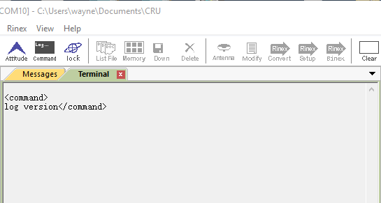
You are not going to forget to press ENTER. Therefore you, my smart friend, will be seeing this screen:
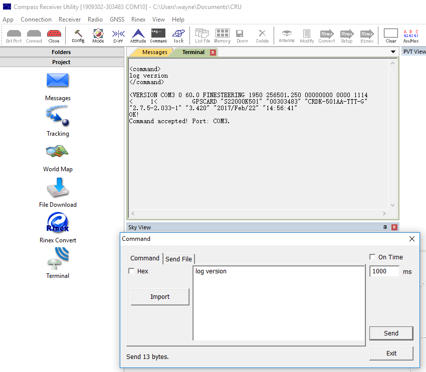
Notice the output in the Terminal tab above. If you see output that looks like this “<VERSION COM3 0 60.0 FINESTEERING…” then you are in business.
It’s quite frustrating that the CRU doesn’t append the newline character for you, but hey, you wouldn’t want it to be easy would you? I think half the battle of working with the K501G card through the CRU is simply specifying the correct port/baud rate and then remembering to append a newline character to your commands.
K501G RTK Rover Commands
Let’s first discuss the configuration necessary to instruct your K501G to output RTK position at 10Hz on port 1 and to accept RTCM corrections on port 2. Cutting to the chase, here are the commands:
FIX NONE
REFAUTOSETUP OFF
UNLOGALL
SET CPUFREQ 624
SET PVTFREQ 10
SET RTKFREQ 10
LOG COM1 BESTPOSB ONTIME 0.1 0 NOHOLD
LOG COM1 BESTVELB ONTIME 0.1 0 NOHOLD
LOG COM1 PSRDOPB ONTIME 1
INTERFACEMODE COM2 AUTO AUTO ON
SAVECONFIG
Let’s give a little color to those commands before moving on.
FIX NONE — If the rover was previously set up as a base station, this clears that out. I once lost several hours trying to figure out why the K501G wouldn’t record movement for more than a minute after startup — turns out it was previously configured as a base station. FIX NONE simply tells the K501G to stop running around pretending to be a base station.
REFAUTOSETUP OFF — Tell the board to not configure itself as a base station. I have no idea if this is necessary, but after the incident above, I became obsessive about ensuring that a rover card isn’t configured as a base station.
UNLOGALL — Instruct the K501G to stop all output on all ports. We just enter this enter this command to ensure we’re dealing with a clean slate — we’ll specify all output below.
SET CPUFREQ 624 — Bump up the K501G’s CPU frequency to handle 10Hz RTK computation.
SET PVTFREQ 10 — Compute PVT data at 10Hz.
SET RTKFREQ 10 — Compute the RTK solution at 10Hz. You may find it odd that you have to specify both PVTFREQ and RTKFREQ. Why is this necessary, you ask? You know better than ask your Mother and I these kinds of questions. Note: ComNav’s documentation says that RTKFREQ should not exceed PVTFREQ.
LOG COM1 BESTPOSB ONTIME 0.1 0 NOHOLD — Ouput the RTK position data to port COM1 every 0.1 seconds. In other words, output RTK data @ 10Hz. If you find the nomenclature of referring to port output as “LOG” a little confusing, then you’re not alone.
LOG COM1 BESTVELB ONTIME 0.1 0 NOHOLD — Output the velocity data to port COM1 every 0.1 seconds.
LOG COM1 PSRDOPB ONTIME 1 — If you want to see the DOP (Dilution of Precision) data every second, then this command is for you.
INTERFACEMODE COM2 AUTO AUTO ON — Instruct the COM2 port to accept RTCM/RTCM3 correction input.
SAVECONFIG — IMPORTANT!!! You have to enter SAVECONFIG for the board to save your changes permanently to non-volatile memory. Stated another way, if you don’t enter SAVECONFIG, the commands you enter will only be in effect ’till you restart the board — at which point the board will revert to the previously saved configuration. Depending on your perspective, I suppose, you will either regard this as a burdensome extra step, or as a slick feature that leaves the door open for bailing out if you’re ever unsure that you’ve entered invalid commands. At any point before you enter SAVECONIG you can simply cut power to the board and all your commands are quietly forgotten.
FINAL REMINDER: Suppose you copy the commands above into the CRU command window, but forget to click ENTER on your keyboard, and thus fail to append a newline character after the final SAVECONFIG command. Here’s what will happen: the K501G will process the first 10 commands (“FIX NONE” through “INTERFACEMODE…”), then it will not process the SAVECONFIG command. The reason for this behavior, of course, is that the first 10 commands have a trailing newline character, but the final SAVECONFIG command didn’t have the trailing newline character.
Now spend a few more seconds working out another really important implication of this: since the board didn’t process that final SAVECONFIG command, as soon as you restart the board, it will revert to your previously saved configuration — discarding all the changes you thought you had made.
K501G Base Station Commands
Now suppose that you want to set up your own base station so that you’re not relying on any external system for corrections (and presumably so that your baseline to the correction station will be shorter). We will consider two different configurations, first we’ll consider the scenario where you want the base station to automatically determine it’s antenna’s location every time it boots up (absolute accuracy to maybe 1-2 meters), next we’ll consider the scenario where you want to explicitly configure the base station’s antenna’s position (absolute accuracy basically as good as your surveyed point).
Both configuration sets presented below output corrections at 1Hz for both the GPS and GLONASS constellations in the RTCM3 format.
July 2019 u-blox ZED-F9P compatibility update
If you’re wanting to use your old K501G cards as base stations for a ZED-F9P rover, here are the messages you’ll want to log (i.e. don’t worry with logging any other messages we mention down in “Scenario 1” or “Scenario 2”):
LOG COM1 RTCM1005B ONTIME 1
LOG COM1 RTCM1074B ONTIME 1
LOG COM1 RTCM1084B ONTIME 1
LOG COM1 RTCM1230B ONTIME 1
End July 2019 update
Scenario 1: Auto Determine Antenna Location
Absolute accuracy: +- 2 meters
Relative Accuracy (accuracy of rover relative to base station): +- 1 centimeter (add 1mm per km distance between rover and base station)
Here are the commands to set up a base station that automatically determines it’s present location every time it boots up:
UNLOGALL
FIX AUTO
LOG COM1 RTCM1004B ONTIME 1
LOG COM1 RTCM1006B ONTIME 1
LOG COM1 RTCM1012B ONTIME 1
LOG COM1 RTCM1008B ONTIME 5
LOG COM1 RTCM1033B ONTIME 10
SAVECONFIG
Scenario 2: Explicitly Declare Antenna Location
Absolute accuracy: +-1 centimeter [depending on 1. Accuracy of surveyed point and 2. Distance of rover from base station (add 1mm for every km between rover and base station)]
Relative Accuracy (accuracy of rover relative to base station): +- 1 centimeter (add 1mm per km distance between rover and base station)
Here are the commands to set up a base station with explicitly declared coordinates:
UNLOGALL
FIX POSITION 28.9823853 -84.2492042 43.89
LOG COM1 RTCM1004B ONTIME 1
LOG COM1 RTCM1006B ONTIME 1
LOG COM1 RTCM1012B ONTIME 1
LOG COM1 RTCM1008B ONTIME 5
LOG COM1 RTCM1033B ONTIME 10
SAVECONFIG
You know that you’ll want to replace the 28.9###### -84.2###### 43.89 with your own latitude longitude height-in-meters values.
That wasn’t too bad, was it? I think a line-by-line explanation of the above commands would be overkill — we’re just telling the card to write the different RTCM messages to COM1. If you’d like an overview of the different RTCM messages, here’s a nice link.
Putting on Your Surveyor’s Hat
You may be wondering how you can get an accurate position of your antenna. Here are a few options:
- Pay to have a location surveyed.
- Make a quick-n-dirty guess by zooming in to the location on a site like this.
- Generate your own super accurate near-survey-quality position with the CRU software via a publicly available corrections source and the K501 RTK card you configured above.
Let’s talk about how to make #3 happen. First you’ll need to find a correction source that’s within, say, 50km — the closer the better. Here is a list of public corrections sources. Here is a big beautiful map of public corrections sources. So, for example, here is the list of public stations for Alabama. If you look at the Alabama link, you’ll notice they give you one IP (205.172.52.26) and then a list of ports to choose from for various location / correction format combinations. I live near Foley Alabama, and I would like to receive corrections for both the GPS and GLONASS constellations in the RTCM3 format. Scrolling down the Alabama RTK pdf, you’ll notice that port 19405 is exactly what we’re looking for.
So now that we know the PORT and the IP for our corrections, it’s time to open up the CRU software and feed those corrections into our K501G RTK card. Remember that when we configured the RTK card above, we specified that we wanted position output on port COM1 and we specified that we would feed in corrections on port COM2.
Here we have another headache with the CRU software — AFAIK you can only connect to 1 port at a time. What this means is that you’ll have to open 2 instances of the CRU — one to read the PVT data from port COM1 and another to feed in the correction data to port COM2. So go ahead and open up two instances of CRU.
Ensuring that the dev board is plugged in and turned on, connect the (USB-to-RS232 adapter / 9Pin cable) from your PC’s USB to port COM2 on the dev board. Now open one of your CRU windows and connect to the dev board by clicking the turquoise “Set Port” button in the upper left.
Assuming you’ve connected to port 2 successfully blue “Diff” icon near the top left-center of the CRU screen.
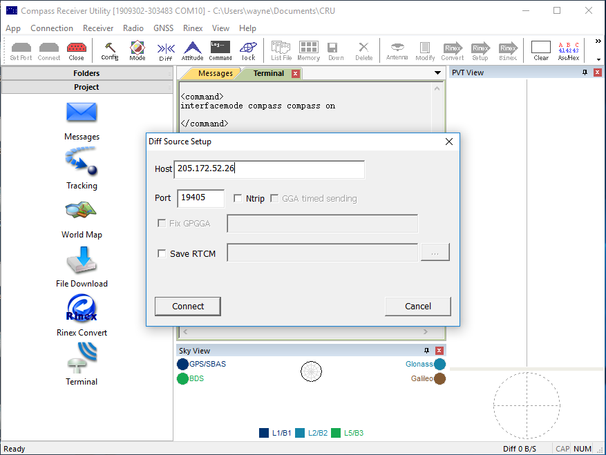
When we click click “Diff” we see a dialog windows called “Diff Source Setup”. Here we will enter the Host IP (you may be able to use a DNS name here like “myslickcorrectionsource.nasa.gov” — I haven’t tested it for DNS) and Port from above. Let’s cross our fingers and click the “Connect” button. If all goes well, here is what you’ll see:
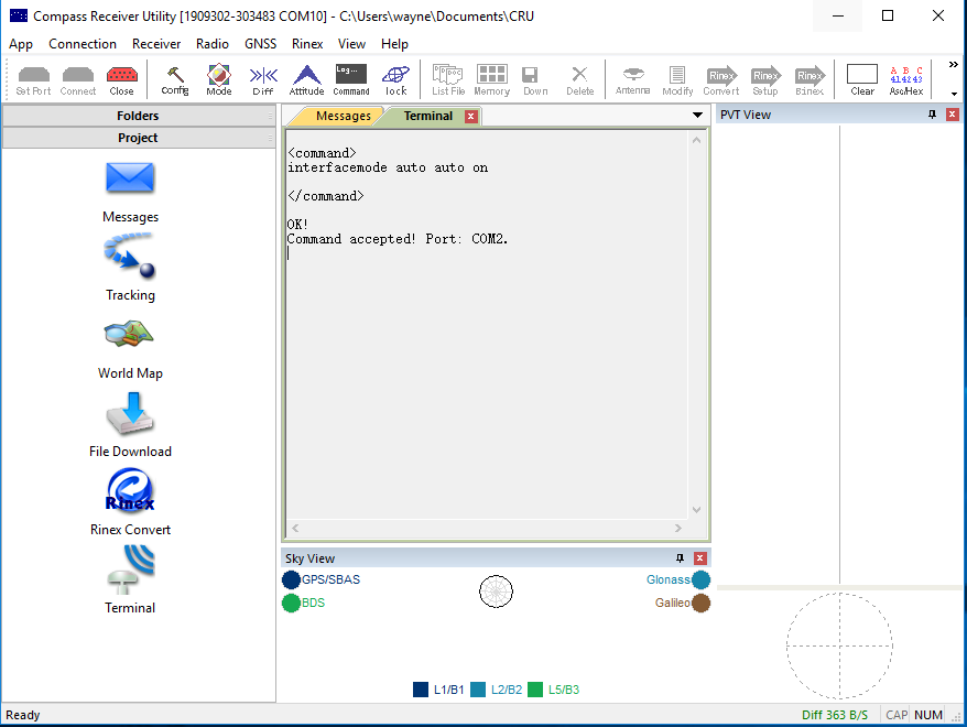
Notice at the bottom right of that screen you’ll see some green text that says “Diff 363 B/S“. You’ve likely guessed that means that you’re receiving corrections from the source specified at 363 bytes per second. That feeling you feel is the warm feeling of free corrections flowing in. That other feeling you feel is anger at having to open up a second CRU window. OK, let’s get over it and open up the second window and connect to port COM1 which we previously configured to output PVT data at 10Hz.
Here’s a screenshot of both windows open in parallel:
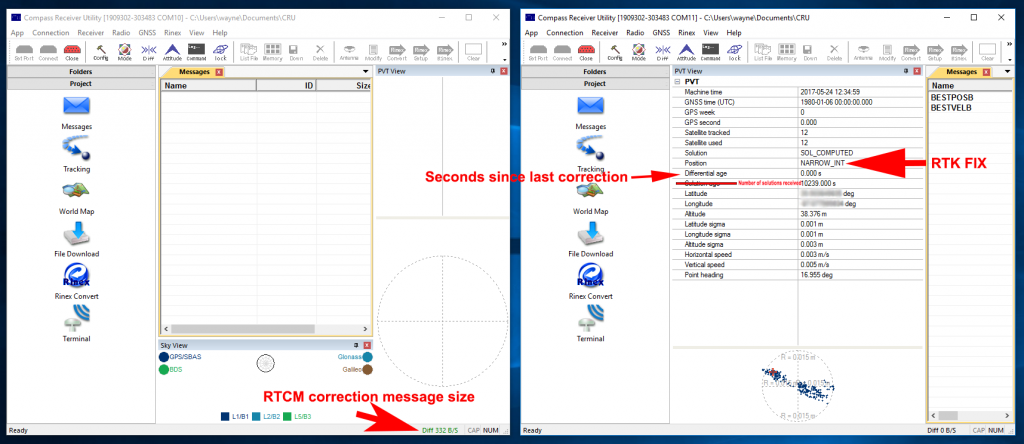
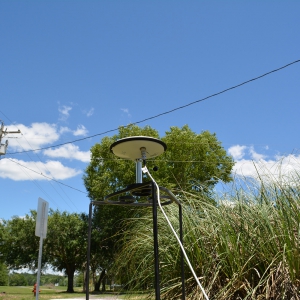
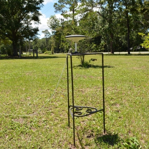
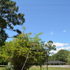
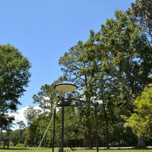
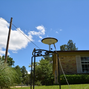
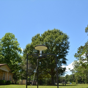
On the CRU screens above I made a few clarifications in red letters. On the CRU screen on the right, when you see the “Position” field’s value reading “NARROW_INT”, that’s K501G speak for RTK Fix. You will notice several hundred points charted at the bottom of that screen are all falling within a 1.5cm radius. Not too bad when you consider we’re on a 16.29km baseline in the middle of the day, on an antenna mounted ~1m above the ground, flanked by tall trees to the north, powerlines to the north, a power transformer to the northeast, powerlines to the east, a big brick house to the south, and various other obstructions as pictured below:
Listen my friends, I’ve heard from several manufacturers since writing the original RTK article, BUT I HAVEN’T HAD ONE OFFER FROM A MANUFACTURER OF EITHER A GPS-ONLY OR L1-ONLY CARD WILLING TO COMPETE WITH THE K501G. I’ll let you guess why that is.
If you think the above pictures represent difficult conditions for a card to hold a RTK fix, then you’re not very familiar with modern L1/L2 GPS/GLONASS systems. I will keep repeating the same line: go ask the surveyors if you don’t believe ‘ole Dad Roby. If you don’t believe them, just buy the cards yourself and brace for awesome.
Speaking of surveyors, and getting back to establishing your antenna’s absolute location, if an actual surveyor were present, they would record several minutes of observation data at your antenna’s location. Then they’d process the data and would likely shave a few millimeters off the error. If, however, you’re OK with knowing your base station’s absolute position on the face of the earth to within a centimeter or two, then the above method should serve you well.
Once the CRU reports “NARROW_INT” (RTK Fix), just note the Latitude, Longitude, and Height displayed and you’ve got yourself an absolute cm-accurate antenna location.
While we’re pointing out quirks with using the CRU software, let’s point out another. If you’re using the CRU to observe data from a K501G at 10Hz (like the right side CRU instance in the dual CRU desktop picture above), within a minute or two the CRU will become bogged down and virtually unresponsive. I suppose the CRU falls victim to a good ‘ole memory leak. A hack to keep the CRU from freezing if you’re wanting to observe PVT data for more than a few minutes is just to dial back the frequency of the output, like this:
LOG COM1 BESTPOSB ONTIME 1 0 NOHOLD
LOG COM1 BESTVELB ONTIME 1 0 NOHOLD
That scales back the position and velocity output to 1Hz. Keep in mind that the card only saves changes when you send the SAVECONFIG command — therefore, you can enter the commands above and play around with CRU all you want, and when you’re done, cycle the power and it will go back to outputting RTK data at 10Hz.
High Risk Move: Ditching the Dev Kit
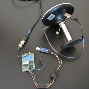
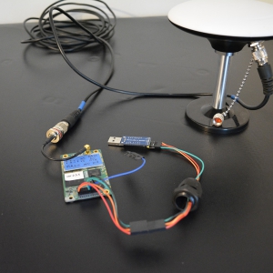
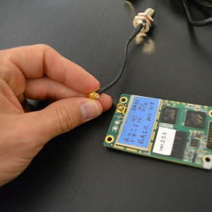
Earlier I told you that I’d show you how to ditch the dev kit and perhaps save a few bucks. Since the ComNav is just outputting serial data, you can communicate with it via a USB-to-TTL adapter. To connect your antenna to the board, you’ll want a TNC Female to MCX Male adapter like this. The K501G’s pins are 2.0mm pins and they couple with a 2x10p 2.0mm Dupont Connector. If you don’t have a 2.0mm crimping tool laying around, you could just pick up some 2.0mm to 2.54 mm Dupont wires to use for hooking up the K501G to your USB-to-TTL adapter.
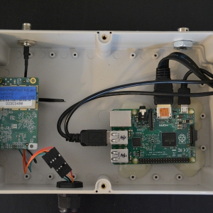
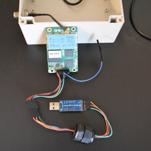
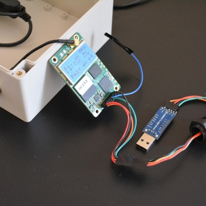
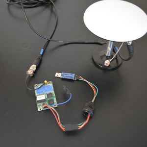
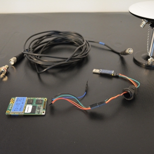
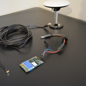
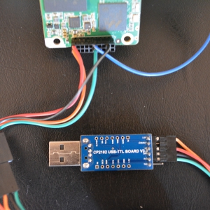
Here is a hacked-together base station following this kind of approach:
Note in the setup above we’re only listening to COM1 on the K501G (we’re receiving corrections on the green wire). The red and orange wires supply power to the board and to the antenna. The black wire is ground. If we wanted to talk to the board, we’d hook up the blue wire to our USB-to-TTL adapter. The function of each pin is covered in the K501G Board Specification.
You may notice in the picture above that I label “1”, “2, “19”, “20” corresponding to the position of the respective numbered pins. I’m paranoid that I will get pin 1 and pin 20 mixed up (and hook up the wrong wires to the pins) and so I write all over the boards to try to mitigate that risk. As always, the labels seem to have a better memory than me.
Of course, you’ll want to be very careful handling and wiring up the board. If you purchased the K501G with your own hard-won cash, then that reminder is unnecessary.
Wrapping Up
After last month’s RTK post, I felt like I owed it to any readers who would venture to purchase the K501G to give you a guide that would, perhaps, save you a fair bit of time and headache when setting up this card. Configuring the K501G is the least fun part of owning it. Fortunately, if you get it right, you shouldn’t have to do it again for a long time (maybe forever).
While I feel like I’ve now discharged an obligation, it may be that this guide leaves you with more questions than answers. If anything is unclear, just leave a question in the comments and I’ll try to respond and/or clean up any ambiguous parts of the article.
I don’t know about you, but I’m ready to get back to building robots.
Until next time,
Sincerely,
Roby


16 Responses
“Listen my friends, I’ve heard from several manufacturers since writing the original RTK article, BUT I HAVEN’T HAD ONE OFFER FROM A MANUFACTURER OF EITHER A GPS-ONLY OR L1-ONLY CARD WILLING TO COMPETE WITH THE K501G. I’ll let you guess why that is.”
Ouch…..actions speak louder than words! lol
GIANT ! Hi Rob, I am Joel van Cranenbroeck a fan of ComNav Technology products and I used their boards but was inhibited to plunge in the wires ! I would like to know more about the TTL-USB converter and also the board you have in one of your pictures … don’t know what it is and the purpose ! Fantastic post … you are a genius ! Many thanks, Joël and greetings from Belgium !
Hi Rob, can you kindly tell me “exactly” the pin on the board socket (1,2, 11, 12, 17 ?) that must be connected with the TTL-USB adaptor ? and which pins on the USB adaptor have to be assigned ? Sorry but I am not that clever to interpret your picture … I guess when you configure the board using CRU.EXE and “SAVECONFIG”, you are only listening for the data correct ? So many thanks ! Joël
Hi Joel!
Glad to meet another ComNav user. In the picture above (http://deepsouthrobotics.com/wp-content/uploads/2017/05/Base_Station_USB_TTL_Wiring.jpg) I’m only hooking up the TTL-USB RX pin to the K501G pin 11 (COM1_TX).
Here are the K501G pin mappings for the COM1 port:
K501G pin 11 == COM1_TX
K501G pin 12 == COM1_RX
In the picture above, notice the blue wire that’s hooked into pin 12 on the K501G. If we connected that wire to the bottom pin (TXD) on the USB-TTL adapter, then we would be able to both send and receive data on COM1. As it’s hooked up in the picture, we’re only receiving data on COM1 — this is intentional because the K501G in that picture is a base station, and we only want to receive RTCM corrections from it. There’s a story behind that blue wire being unplugged — the Raspberry Pi I hook that receiver to sometimes seemed to put some garbled communication on the port, so I just unplugged the wire in lieu of worrying with what kind of crazy random message the Pi may be sending to the K501G.
But, back to the USB-TTL picture above, if you connect the blue line to the open USB-TTL TXD pin on the bottom, then you’ll be able to plug that adapter into your PC and you can configure the K501G via the Compass Receiver Utility.
Does that answer your question?
–Roby
Hi Rob,
Don’t know if my message passed ? I was asking you about the exact wiring you are using for connecting the pins of the K501G and the TTL-USB adapter … Sorry, I tried to follow the colors but I prefer to ask you to confirm … That’s an incredible great work you did and for sure I will give a trial as I have a K501 board here 🙂 So many thanks for your generosity in sharing that beautiful step by step assembly explanation !
Dear Rob,
Oops yes it entirely answered my questions !!! Sorry I was looking for and didn’t see it at first ! I am over excited to try 🙂 So many thanks again and again !
Hello Rob,
I’m with Ardumower (open source robotics mower), and we are considering to purchase some ComNav modules too. Currently, I’m testing the Piksi Multi (L1+L2 RTK) modules under challenging environment ( https://www.youtube.com/watch?v=T2dnQaqobJw ) – Do you think the ComNav modules could perform better in my video? Btw, great article! Regards, Alexander
Hi Alexander,
Ardumower is a great project and your site has been a gold mine of information for years. Good to see your video of the Swift Multi — from the limited camera perspective, I would not call that environment “challenging” for a reputable L1/L2 GPS/GLONASS system.
Have you tested the u-blox M8P (with v3/v4 firmware update)? You might find that the M8P would demolish the Multi’s performance in nearly every facet except initial cold-start fix time.
RTKLibExplorer has recently compared the Multi to a lowly u-blox M8T running RTKLib. His results were in line with all independent reviews I’ve seen of both products.
Keep up the great work!
–Roby
Hi Rob,
Thank you for sharing your knowledge of the ComNav product.
I am interested in using the ComNav in a drone using a Pixhawk Flight Controller for RTK Precision Navigation. Have you successfully interfaced the ComNav as the primary GNSS receiver in this manner.
I am also interested in logging a PPK File for a backup method for geotagging aerial photographs if the RTK Fixed Solution experiences k
a hiccup during one of my flights.
Randy,
Yes I’ve used Pixhawk with the ComNav K501G for missions totaling several hundred hours. It’s a great system, and the driver interfacing the K501G to Pixhawk is provided in the stock Ardupilot software.
I haven’t yet got into PPK world, but RTKLibExplorer seems to post PPK musings fairly often — you’re likely already familiar with his blog.
–Roby
Hi Roby,
Thanks!
Do you happen to know if the K501G has the capacity to output all the requested
parameters to complete the “Vertical Velocity” aspect of the Pixhawk GPS
Navigation as requested via Novatel/Tersus/ComNav GPS driver for ArduPilot?
Its probably not of much interest to you and the awesome mower project.
But it is pretty important to those of us with airborne equipment…
When your mower goes airborne, I’m sure you will be reaching for that “OFF” toggle switch
orientated in the correct direction and not so interested in those details…
Hi Roby and Randy,
I am also interested in interfacing K501G with Pixhawk for airborne (multicopter).
Do you ever see “bounces” in the GPS position ?
With the M8P, depending on the correction it receives, it can jump from several meters like a glitch .
Greg,
Once the K501G has a fix, my experience is that it’s quite solid. Distance to reference station really matters.
I’d like to post some kind of controlled real-life comparison between the u-blox M8P and the Comnav K501G, but alas, consulting work has taken over lately.
For airborne work, I know that Henrik at http://www.trueflighttech.com/ has a lot of experience with the M8P and with L1/L2 systems. You might want to give him a call.
–Roby
Initial look at the ComNav K708 receiver – rtklibexplorer
[…] Both receivers have decent reference manuals to describe their command set but I also found this Hackers Guide to the K501G from Deep South Robotics quite useful for getting […]
Hello Rob,
Thank you for the great post.
I have the same interest that has Randy.
I am interested in using the ComNav in a drone using a Paparazzi Flight Controller for RTK Precision Navigation.
I would also like to log a PPK File for geotagging photographs in photogrammetry.
Do you have any idea about this integration?
Is it better that the Neo-M8P?
Thanks
Hi Rob,
I’ve seen that Comnav released the K726 board a while ago: an RTK board with dual antenna and thus heading information! Heading tech specs (http://www.comnavtech.com/download/K726%20OEM%20BOARD-ENG.pdf) are excellent, like the other specs:
Azimuth: (0.2/R)° – where R (in meters) is the distance between the antennas
Roll or Pitch: (0.4/R)°
What do you think about it? Will it be a success like the K501G?