
Rover 1 has been a fun project, but Rover 1 is too small for our ambitions. It’s time to start working with a wheelchair-based robot platform. However, before we make the move, let’s make one last modification to Rover 1.
Voiding the Warranty

I want to test out a cheap 60 amp (2x30a) dual motor controller (hereafter called “M60”) available on eBay that I’ve not seen reviewed elsewhere. Is it possible that this motor driver is a viable alternative to the venerable $125 Sabertooth?

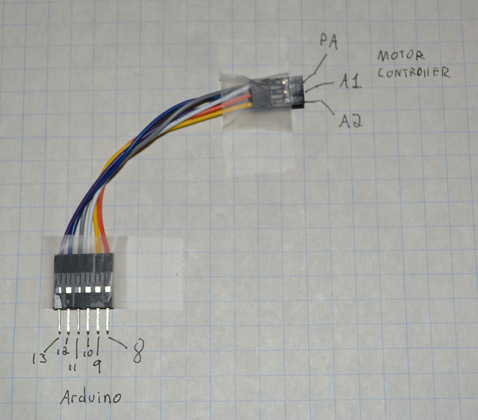
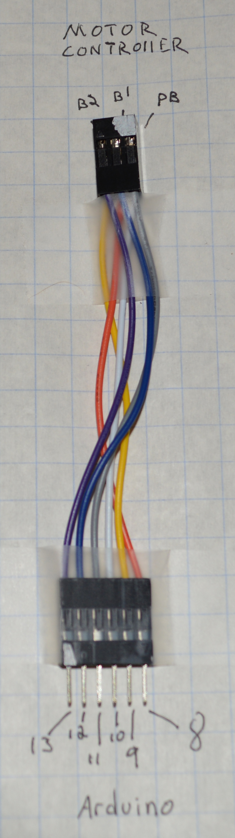
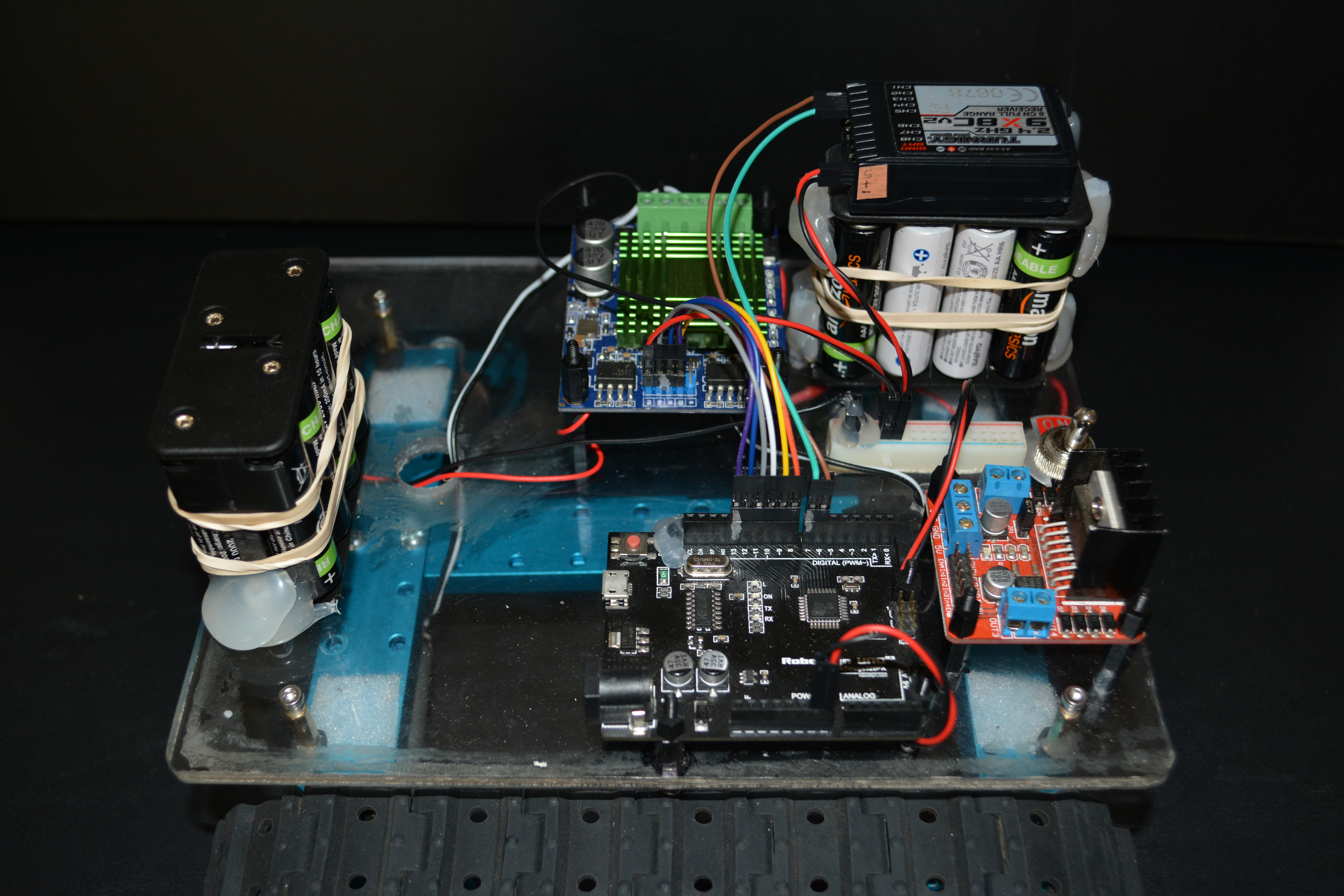
Now think back to your 9th grade Mandarin class and review the spec sheet for the M60. If you don’t remember Mandarin, I’ll give you a quick hint: the 6 control pins (labelled PA, A1, A2, PB, B1, B2) behave just like the L298N control pins (labelled ENA, In1, In2, ENB, In1, In2). In other words, we’re going to switch over from the L298N motor controller to the M60 motor controller without touching a line of Arduino code.
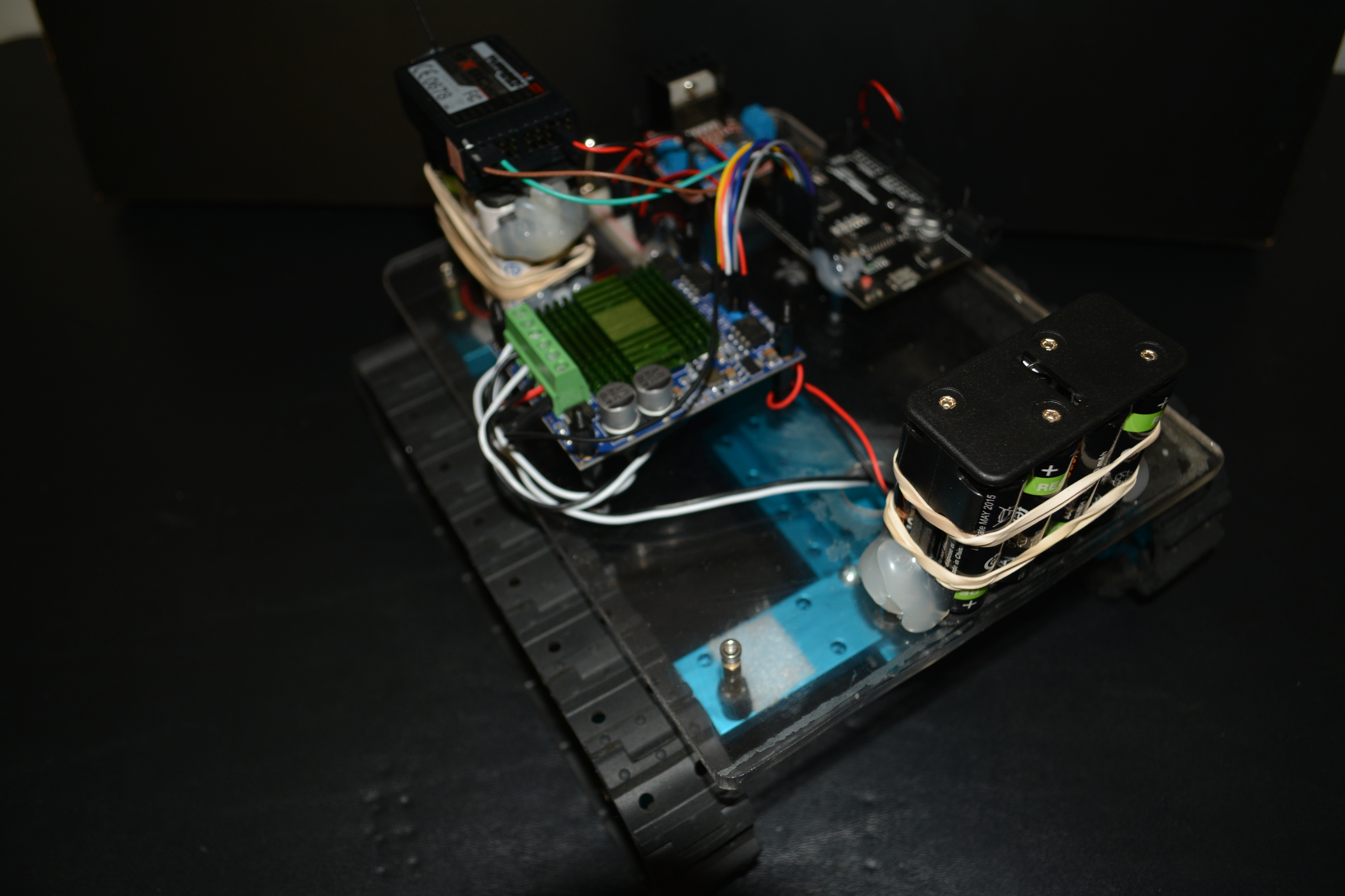
Now, you’ll notice that the voltage range on the spec sheet is 12v-30v. This means that we are compelled to ramp up the voltage for Rover 1. This is accomplished by adding another 8-place AA battery holder to the platform and wiring it in series with the existing battery holder. This should give us a potential voltage of 16*1.2v = 19.2 volts. In practice, due to limitations of the batteries and loss in the driver, this will give us around 14v at either motor. Keep in mind these are 6v motors. Clearly, we are violating sensible design behavior.
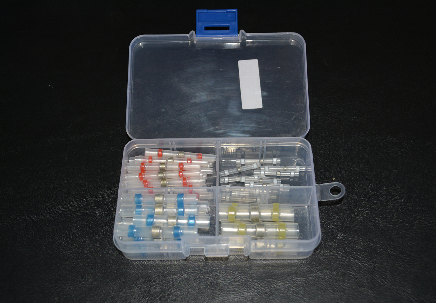
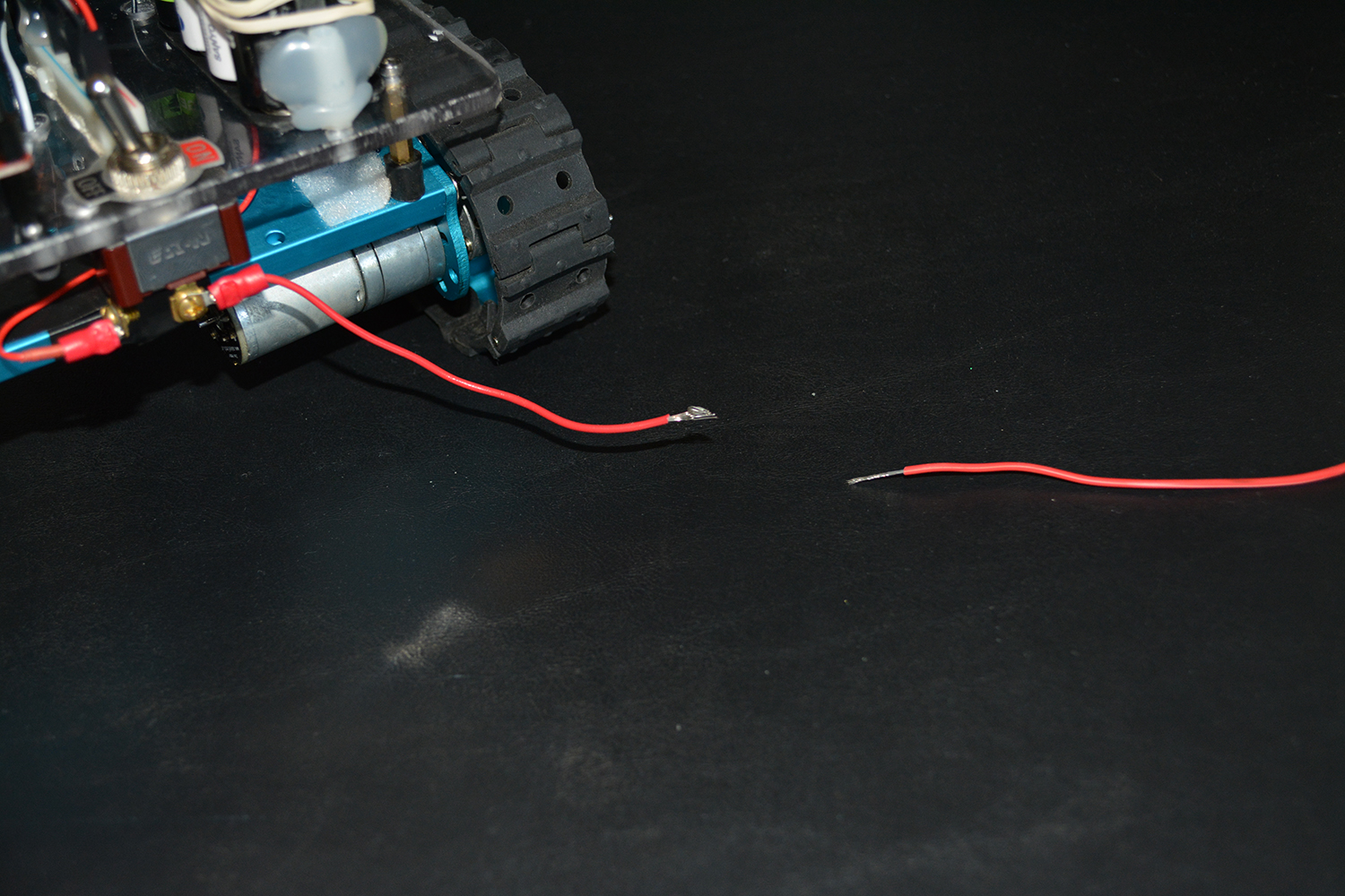
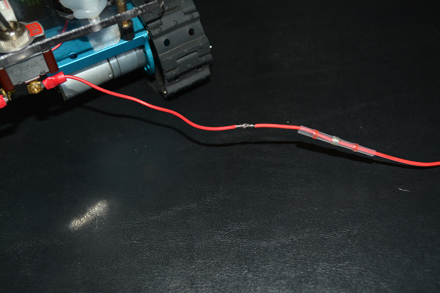
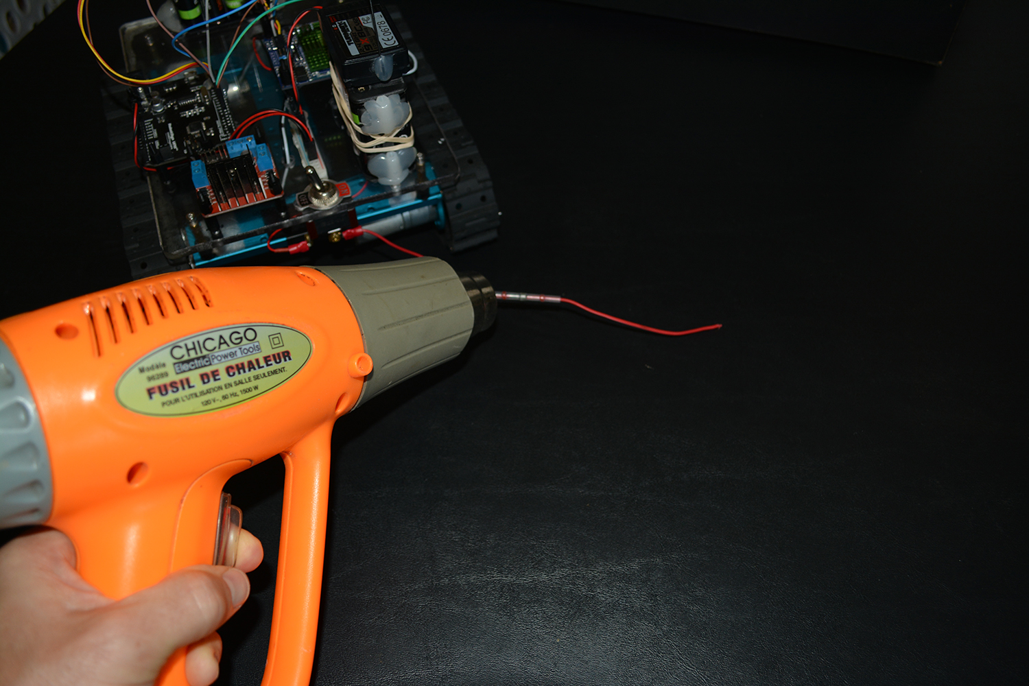
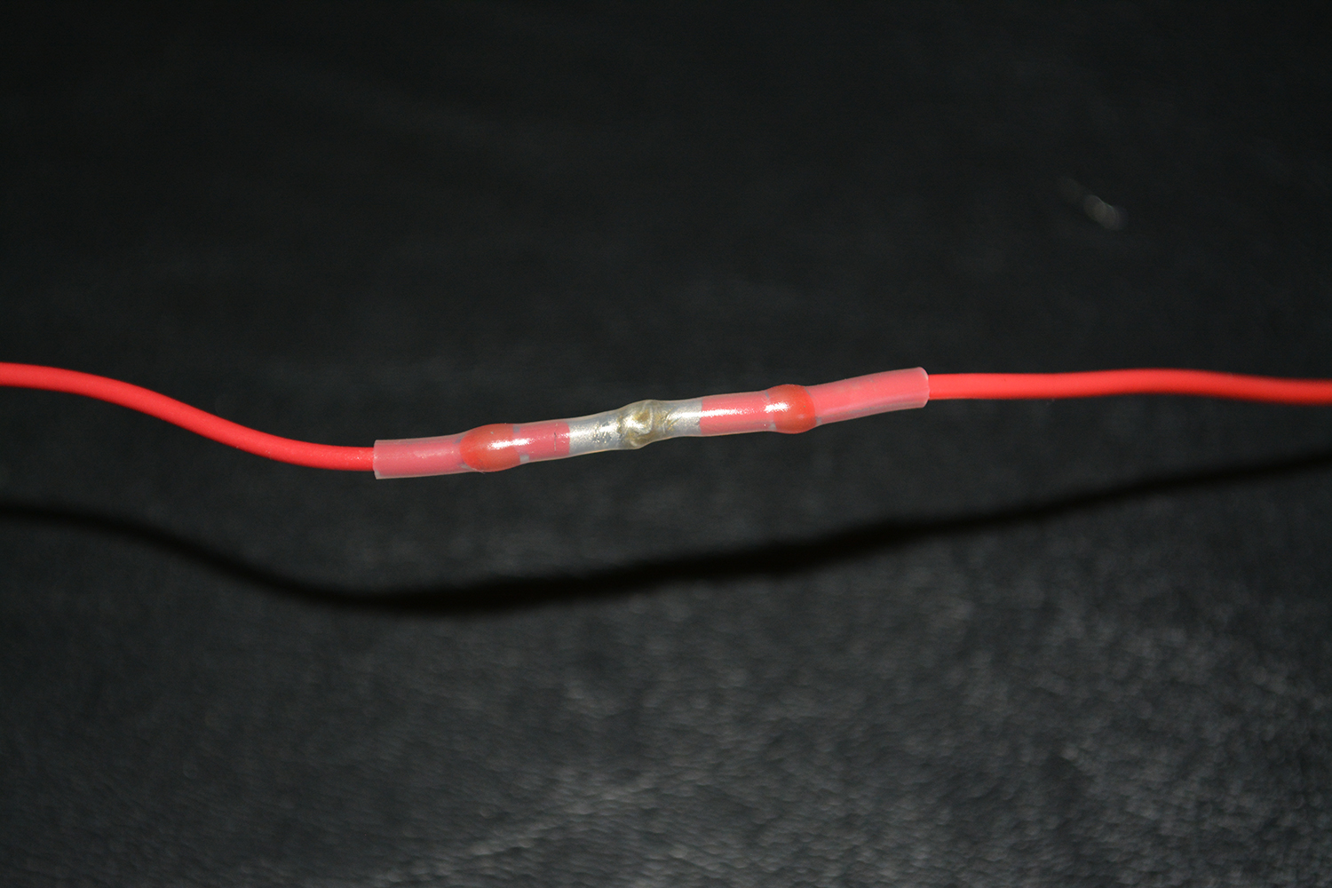
It turns out that the positive wire from the battery to the M60 needs to be a little longer. This gives me a perfect opportunity to try out some of the fancy new heat shrink solder connectors that you can pick up just about anywhere including Amazon. I purchased these several months ago, but have been suspicious of their fitness, and haven’t tried them out ’till now.

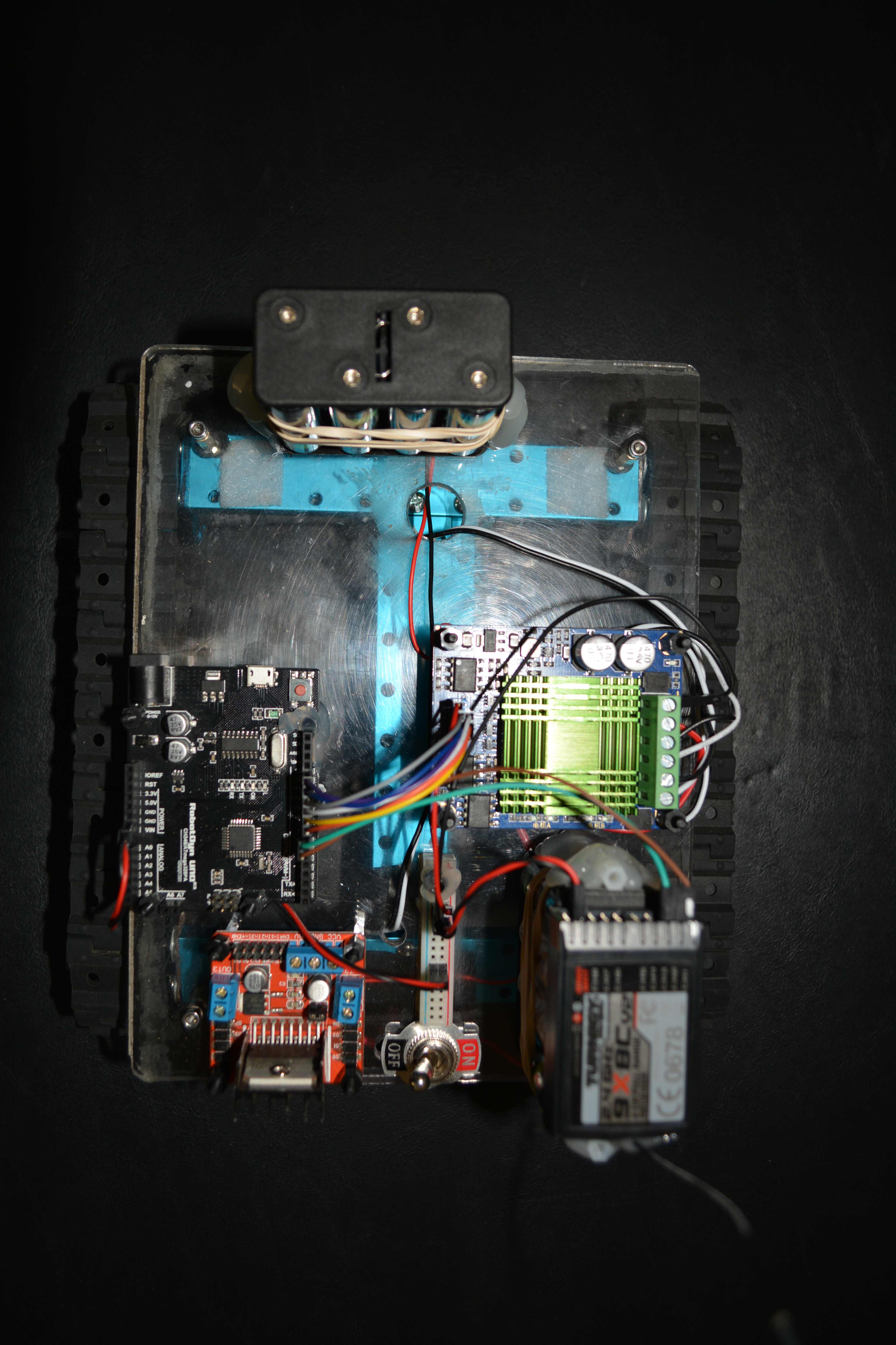
Check out these pictures of Rover 1 fully assembled:
The boys like helping, particularly during the testing phase:


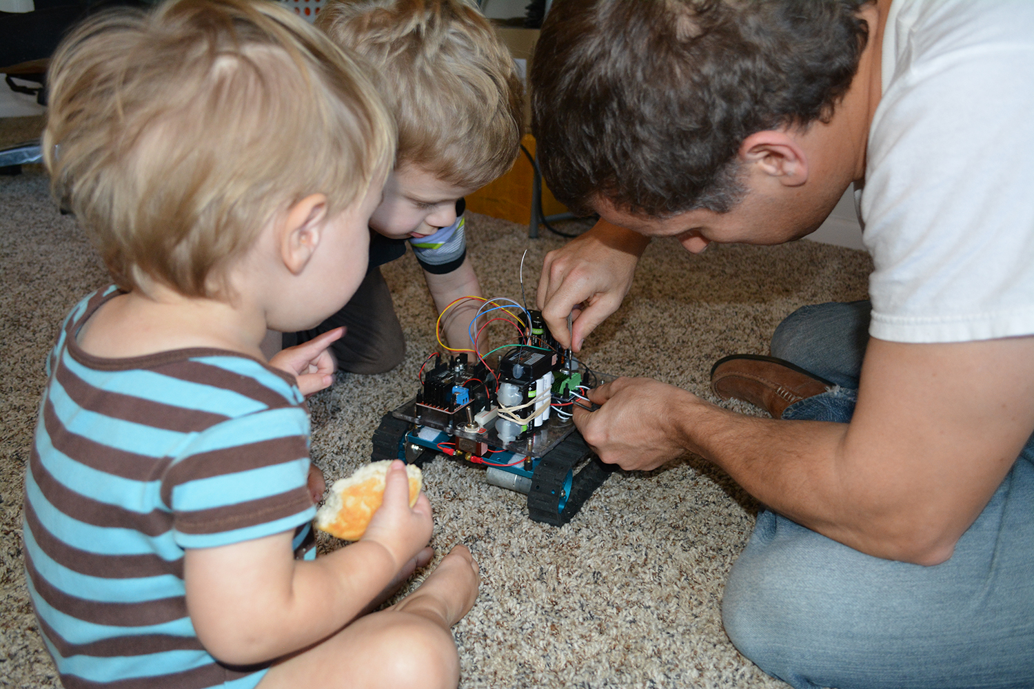

Here’s a little video of it running around the back yard. Note that the oldest boy is quite dejected since he’s not driving.
Wrapping Up
Somehow Rover 1 appears to have survived exceeding the motor’s recommended voltage by over 2x. Let’s quit while we’re ahead! Next time we’re going to pull the M60, Arduino, and radio off Rover 1 and try our hand at a big-boy robot.
Here’s looking forward to seeing you then,
Love,
Roby
2 Responses
Like those wire connectors you used. Never seen them b4. Waterproof??
They claim they’re waterproof. I’m curious to see how they hold up over time.