Let’s start this off with some outtakes from playing chicken with Rover 2:
Now some of you guys are thinking that’s irresponsible. Agreed. But hey, ever thought you may get to be 90 years old and wish you’d been a little irresponsible in years prior?
So the title suggests that things are going to go poorly. Yes, in the end we have trouble with the driver, but we’ll see that perhaps the problem was user error.
Tweaking the Code
So let’s talk about the changes we made to the Arduino code to run Rover 2. You’ll find all the code for Rover 2 available on GitHub. Here is the full source for the Arduino sketch that we will now discuss.
First I want to call your attention to the pin mappings:
  // M60 to Arduino
  // right motor
  const int pb = 10; //pb should be 9 or 10 if you plan to call setPwmFrequency(pb, 8) for noise reduction below
  const int b1 = 8;
  const int b2 = 13;

  // M60 to Arduino
  // left motor
  const int pa = 9; //pa should be 9 or 10 if you plan to call setPwmFrequency(pa, 8) for noise reduction below
  const int a1 = 12;
  const int a2 = 11;
Note that the section above is slightly changed from the L298N code. We moved the pwm output (pa and pb) to pins 9 and 10. The reason for this is that when I drove the M600 with the Arduino, there was an obnoxious buzzing sound. A quick google suggested that the noise could be reduced by adjusting the PWM frequency for the PWM pins. Well, it turns out that adjusting PWM frequencies on pins other than 9 or 10 disrupts the Arduino timing functions that we rely on. So can you adjust the frequency of pins 9 and 10 with no consequences? Nope, this messes with the functionality of the Servo library. Score for us, we’re not using the Servo library.1
  leftMotorSpeed = constrain(leftMotorSpeed, -254, 254); //reduce to +-254 for M60
  rightMotorSpeed = constrain(rightMotorSpeed, -254, 254); //reduce to +-254 for M60
While the L298N considers a pwm value of +-255 as a maximum, those values cause the M60 to stop. So we adjusted the max to +-254 and everything seemed fine, until…
I can’t remember the exact sequence of events the first time it happened, but I was coding up the Arduino M60 driver and wiring up Rover 2 and all of a sudden I hear something like a spark and I saw smoke come off the driver. I really don’t remember this time if I was uploading code to the Arduino or not (more on this later)…
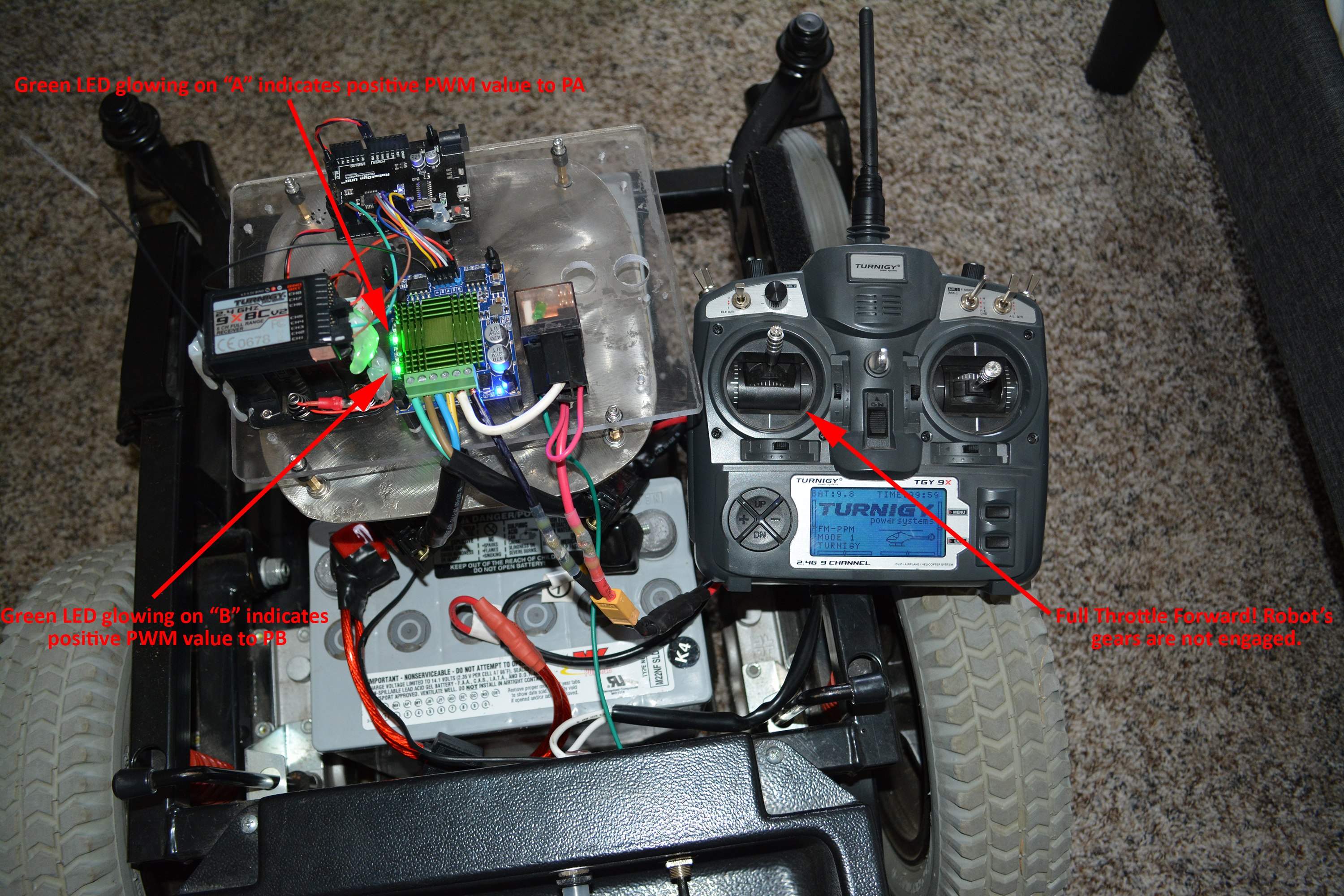
So, after tinkering with that Arduino code with Rover 2’s gears in neutral, it seemed that the M60 was powering the motors quite well. But then I noticed something odd. Here are a few pictures to show you how the M60’s LED lights behave when you go forward or reverse:
M60 Full Throttle Forward
M60 Full Throttle Reverse
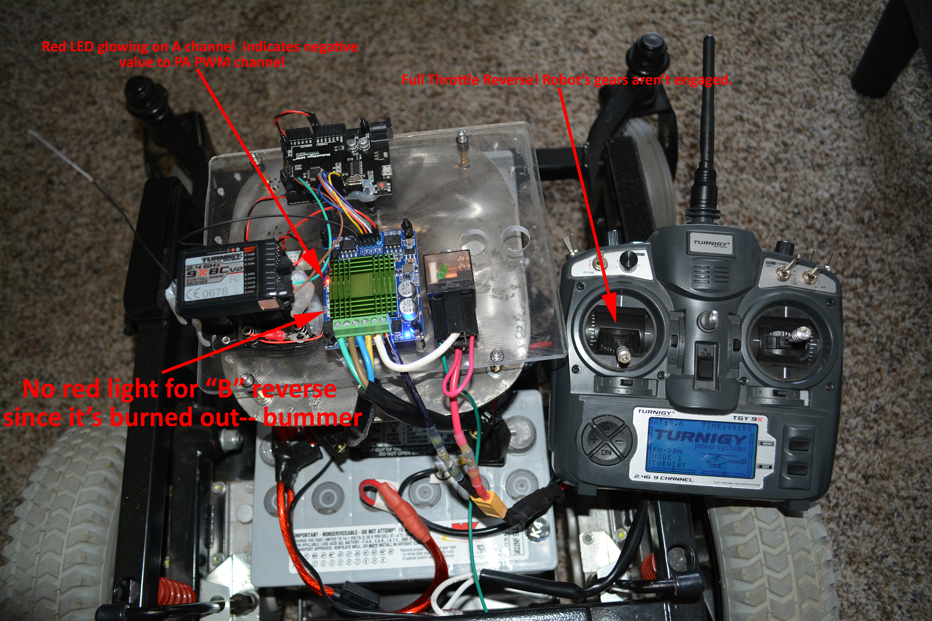
So there’s a problem! For some reason the “B” channel light is not turning on. Also, regrettably, channel B is not sending voltage to the right motor in reverse. Remember that reverse was working when we ran Rover 1 with the M60. Therefore, after the smoke incident mentioned above, I assume that I must have somehow fried M60’s ability to do reverse on channel B. Bummer!
Hard Test Run
OK, so we only have reverse on 1 wheel. Hey, who says you can’t have a little fun going forward? We took Rover 2 outside and drove it around for ~45 minutes. It performed flawlessly (minus irreversible right wheel). I drove it as hard as I could and put my hand on the M60’s heat sink — it was only a little warm — quite impressive. I drove Rover 2 down the little side road next to our house (not the big highway you see in the video), probably 200 meters away (it was quite blurry for a near-sighted fellow who eschews glasses) and only turned it around because Mrs. Roby was nervous about the robot being so far away. I was curious if the Turnigy radio would lose range, but it performed perfectly.
Now that we had tested Rover 2 and the M60, it was time to come back inside and make a few code tweaks…
Burning Out Channel “A” Reverse: Eureka!?
Here is the fateful order of events I now want to present into the public domain of M60 driver knowledge:
- M60 motor driver is turned on and powered by 24v power source
- M60 motor driver is connected to Arduino as indicated in the pin mapping above
- Mac is connected to Arduino via USB
- Code is changed in Arduino IDE
- Code is uploaded from Mac to Arduino
- !!!!!!M60 SPARKS, SIZZLES AND SMOKES!!!!!
More smoking and sparking than last time! It happened right after I uploaded the Arduino code (think less than 1 second) and it lasted for a couple of seconds. Could it be that the Arduino is putting garbage output on the pins and the M60 doesn’t have protection from errant control pin input?
Wrapping Up
The M60 driver turned out to be a real adventure! You can tell from the videos above that it effortlessly runs the rover. With the exception of the unfortunate reverse blowouts, it performed quite well.
Let’s end both our M60 experiment and this blog post on on this note. Next time we’re going to make the move to the time honored Sabertooth driver. Why do all the cool kids rave about the Sabertooth controllers? I think you’ll see.
Until then,
Sincerely yours,
Roby
Notes
- Keep in mind that “M60” is the alias we’ve given to the mysterious driver who elsewhere goes by the full name “60A High Power MOS Dual Channel H-bridge DC Motor Driver Module”
- The considerations for adjusting pin frequencies are outlined here in the documentation for the setPwmFrequency(..) function.
- When discussing this “M60” driver, there are so many unknowns (and hence, caveats) it’s comical. For instance, if you look at the different M60 drivers on eBay, you’ll see there are slight variations between some of them. My M60 has 2 capacitors. Some of the new ones (like this one) have 3 obvious capacitors and a blue cylindrical component labelled “221” which may also be a capacitor — either way my M60 doesn’t have it. A manufacturer spec sheet for this driver would be wonderful: if some kind reader either knows Mandarin or has ninja Google skills, that would be a great find.
Leave a Reply