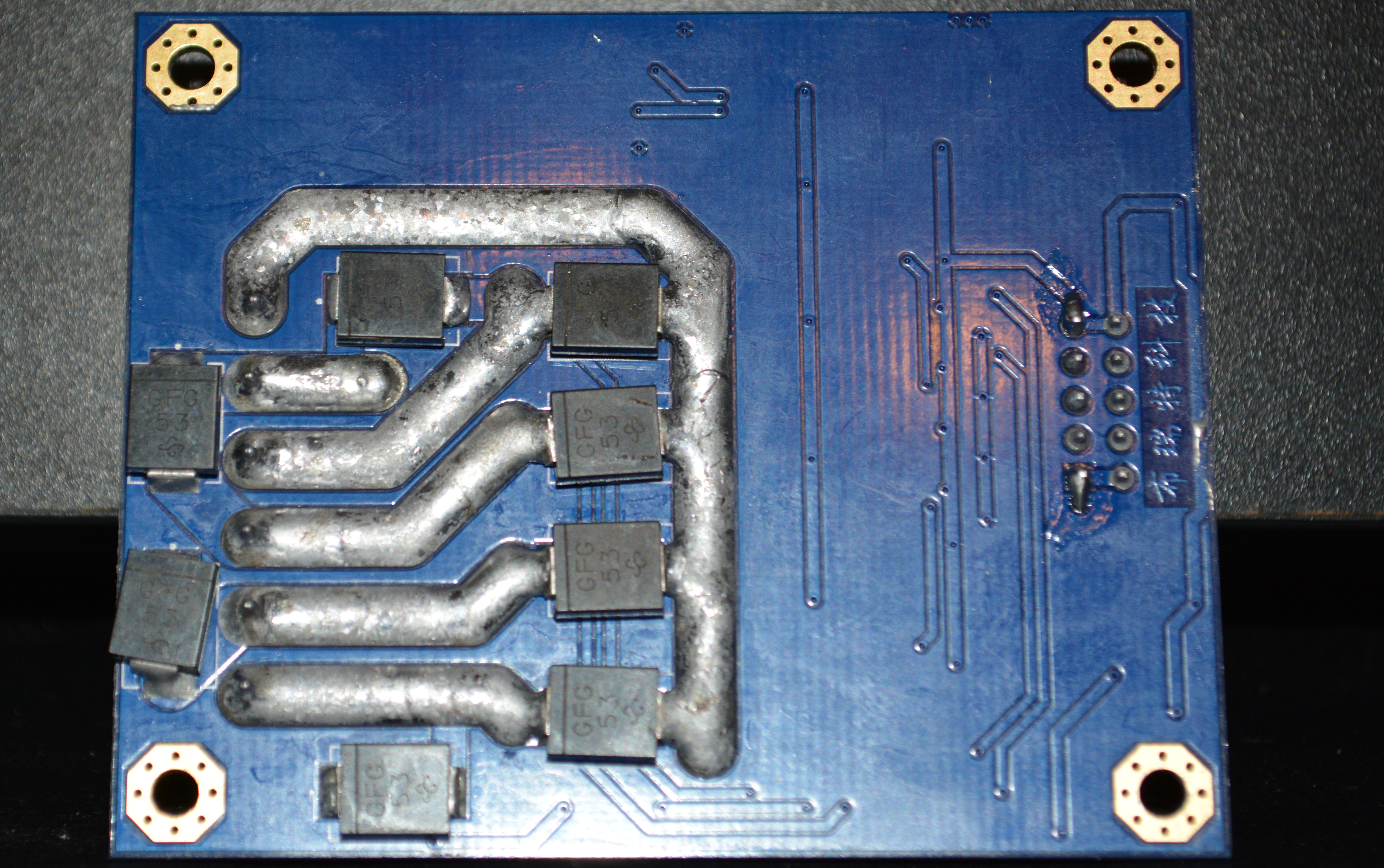
Welcome back fellow, future, and potential robotocists! In our last post we played with a little fire while programming the M60. While taking the photo above I became curious what was beneath the heat-sink for the M60, so here we present State Exhibit A37:
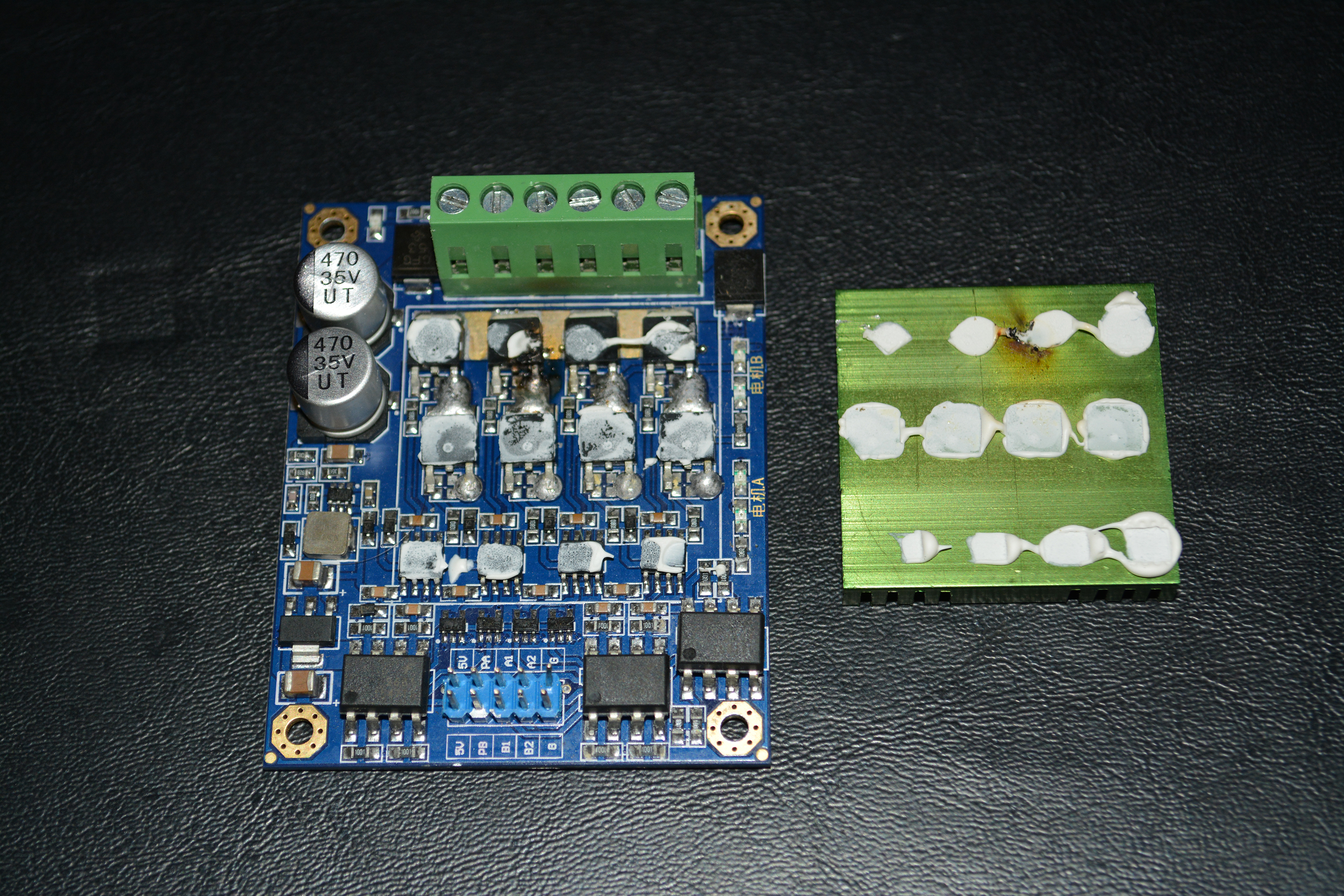
You can probably see the burned component in the upper middle of the board below the green terminal bank. I assume that’s a MOSFET transistor — if any reader with an electrical background would like to inspect the image and report back, I’d love to hear from ya!2
You likely realize that this enigmatic M60 has now found it’s way into the last 3 posts of this blog: like a bad girlfriend, we just can’t let her go! Now listen here my sons: you don’t want to marry the M60. I know she’s mysterious and wild, but you’ve got to trust ‘ole Dad Roby on this one: the Sabertooth is the girl for you.
Sabertooth & Robot: A Well Arranged Marriage
Exchanging the M60 for the Sabertooth means eliminating the Arduino: we wire the Radio receiver directly to the Sabertooth and configure with a relatively friendly Windows application called DEScribe — more on this shortly. Let’s check some pics from the Sabertooth retrofit:

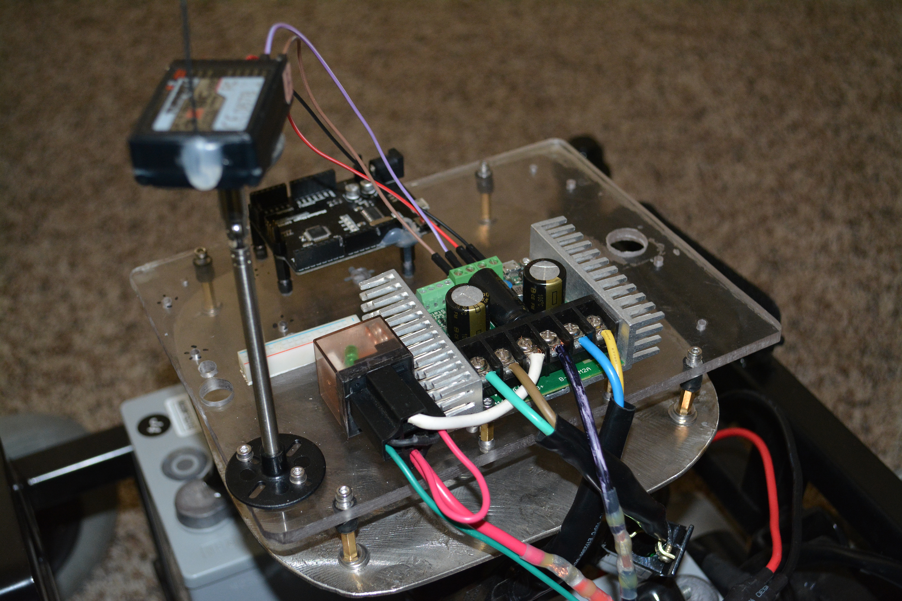
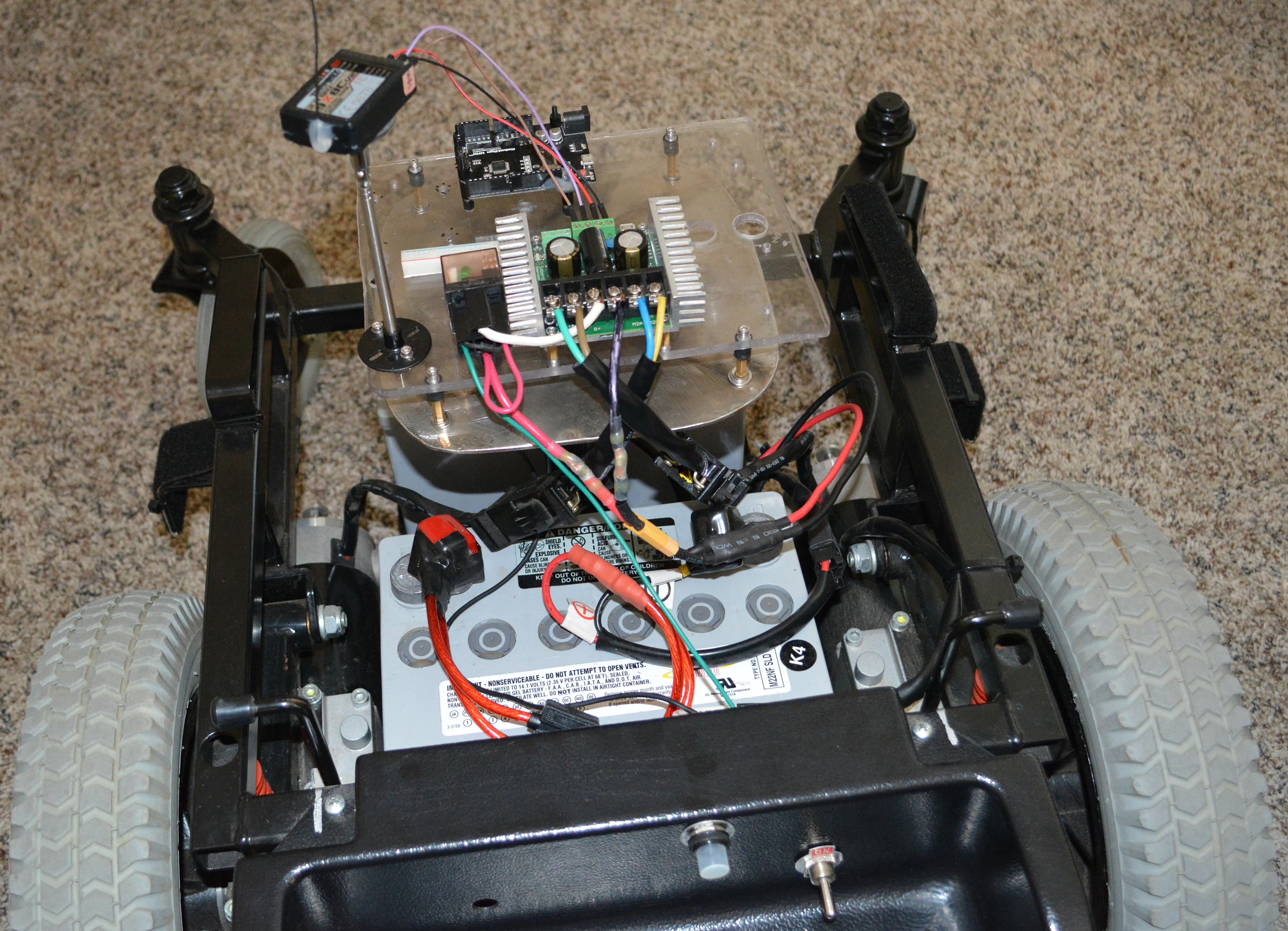
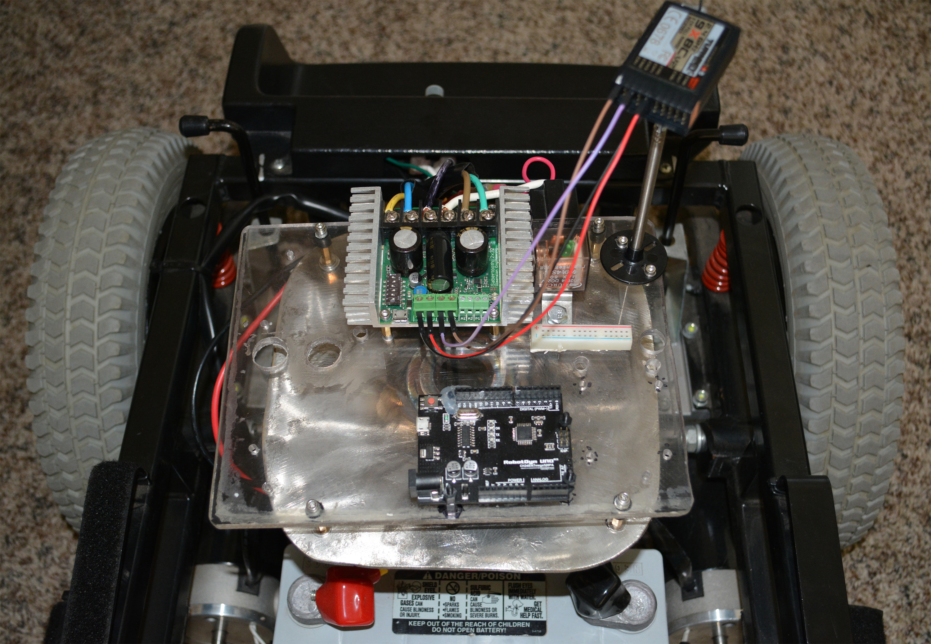
A few comments/clarifications. First, if you look closely at the pics and follow the green/brown wires from Sabertooth M1A/M1B, you’ll notice that those wires trace down to the right motor. Accordingly, if you follow the blue/yellow wires from Sabertooth M2A/M2B you’ll find them connecting to the left motor. For a simple man like me, this is a headache; specifically, I wish the right motor’s wires went to right side of the sabertooth and the left motor’s wires went to the left side. Perhaps there’s a way to configure this in the DEScribe software, but I haven’t found it.
You’ll notice 4 breadboard wires connecting the Sabertooth to the radio receiver. These are 5v, Ground, Steer and Speed. The Sabertooth (like the M60) magically anticipates you might like to have a 5v power supply and provides an auxiliary 5v and ground. Remember that Steer and Speed come across the air as two independent channels — we’re going to instruct the Sabertooth to take care of mixing these into appropriate left and right motor current.
How Do I Love Thee?
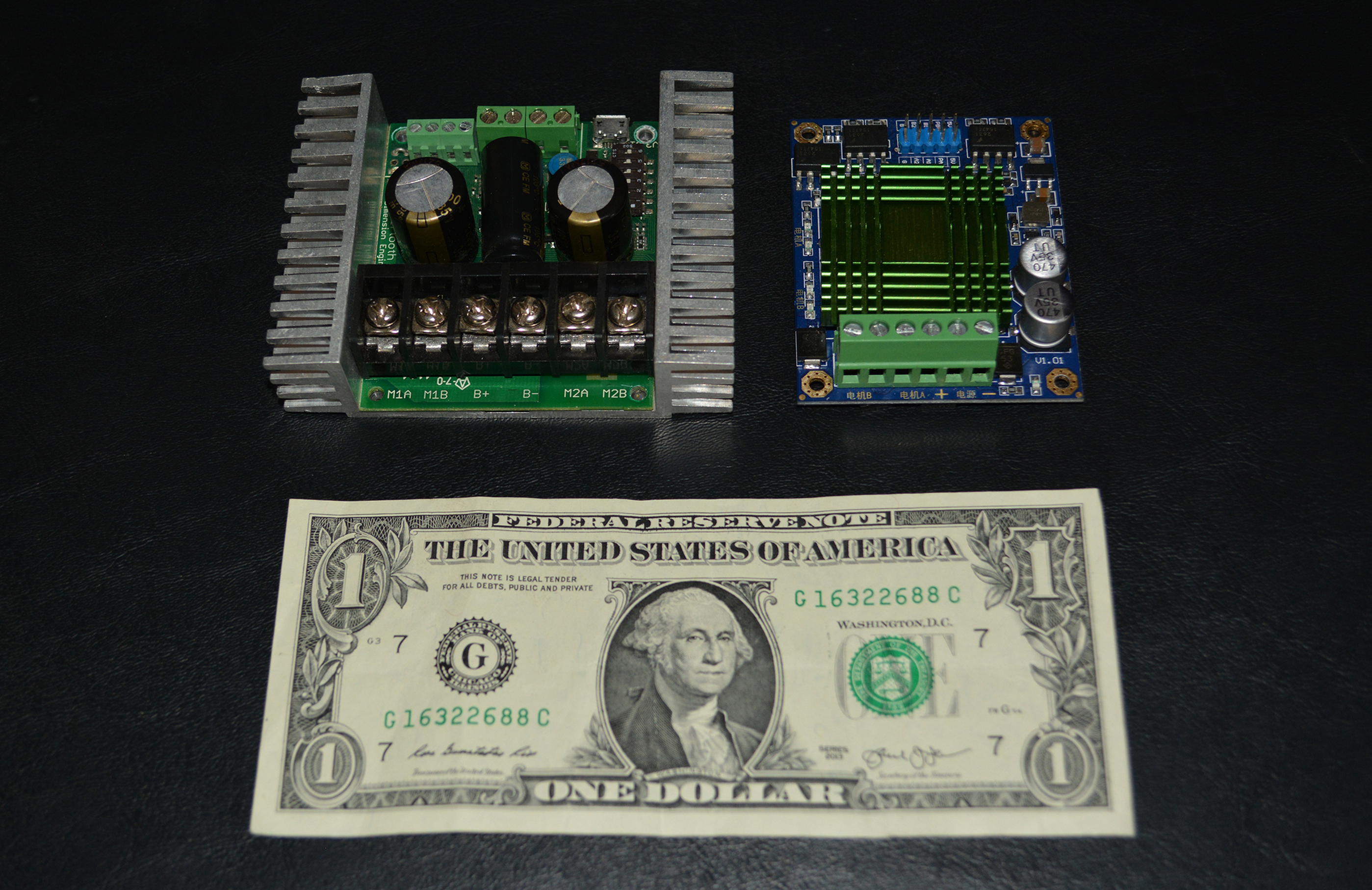
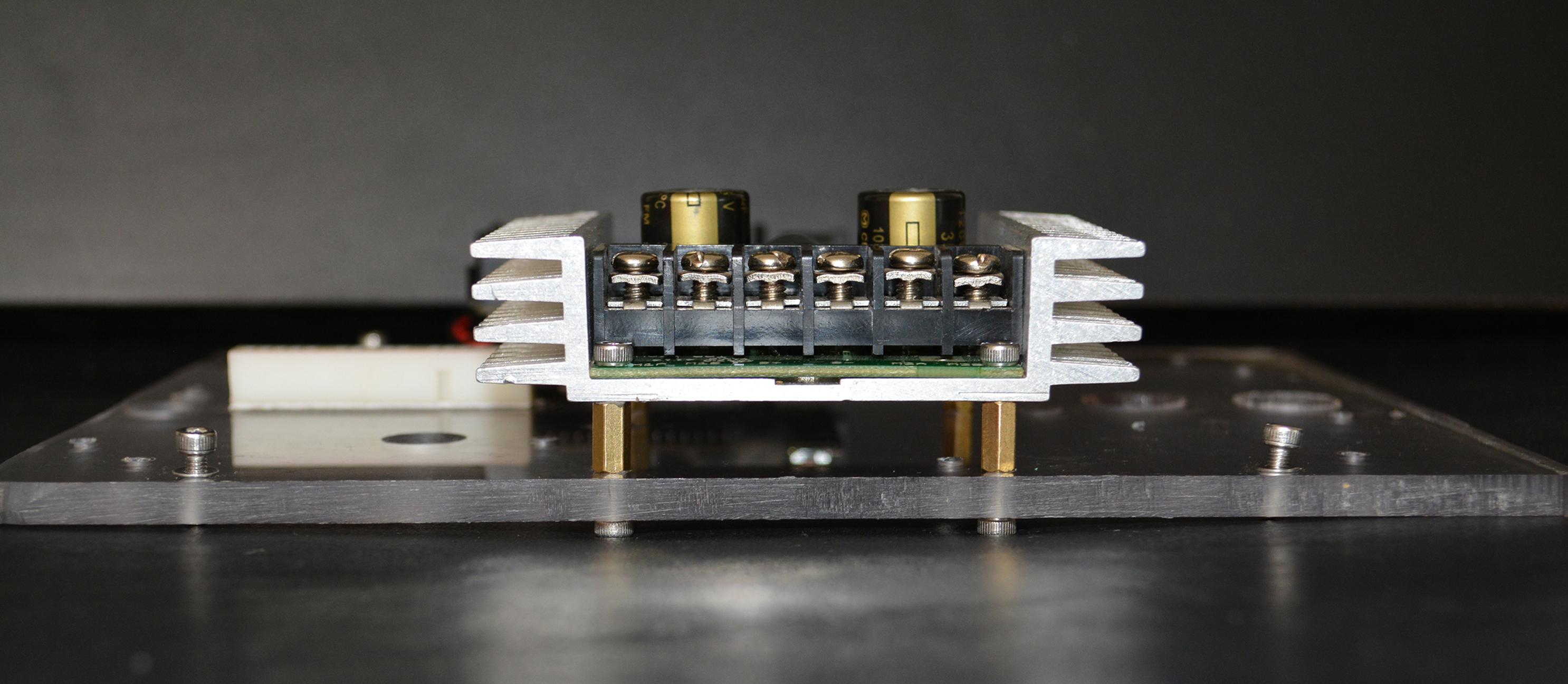
So what’s so great about the Sabertooth? Several things. First, look again at the picture at the top comparing the drivers and notice the difference in the terminal block size. The Sabertooth easily accommodates 10 AWG wire. Good luck with that on the M60. Here are photos with both drivers referenced against red 10AWG wire:
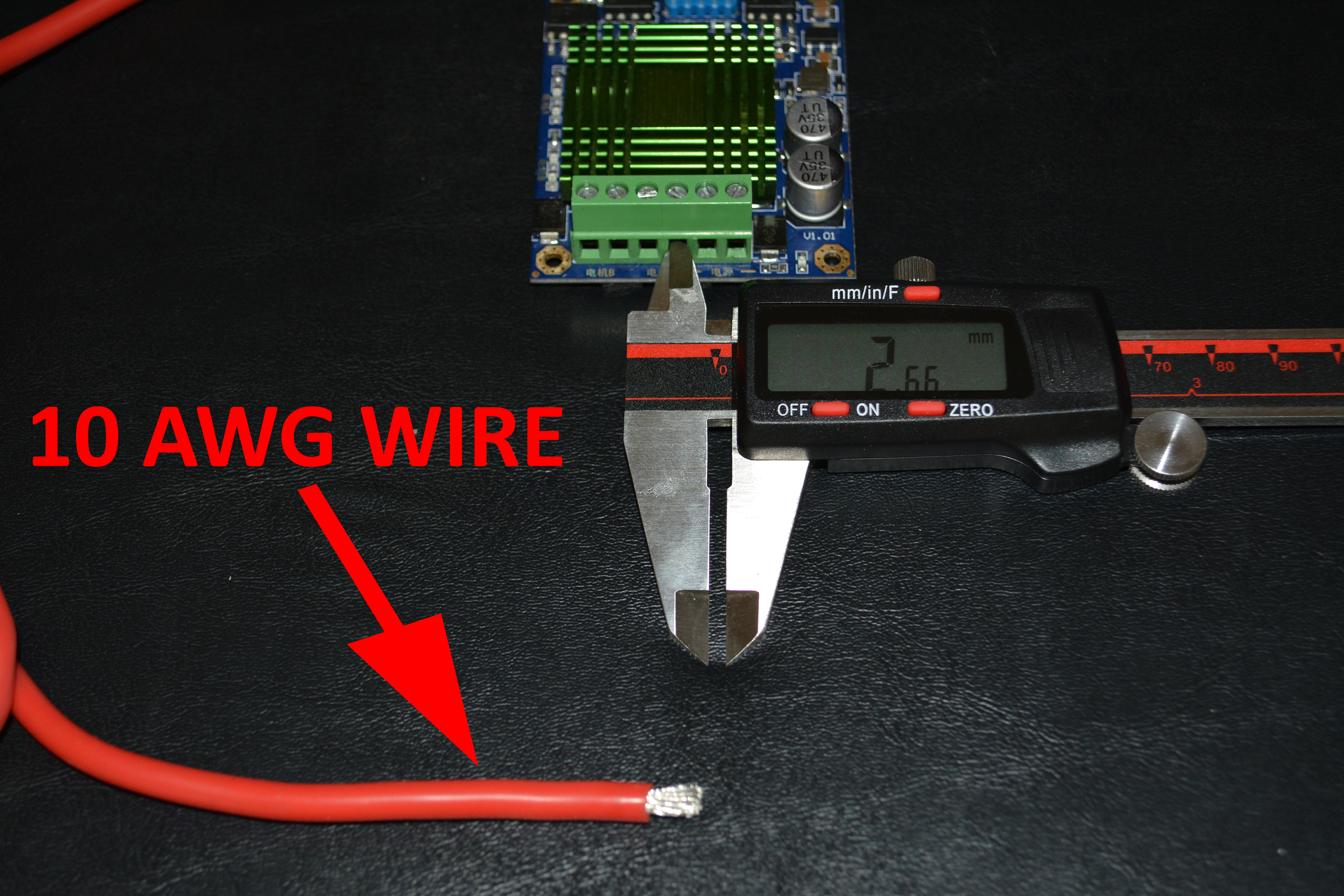

The M60 uses 5.08mm pitch connectors like these. Max wire size rating is 12AWG. The big luxurious terminal bank in the Sabertooth feels like flying first class.
Aesthetically the Sabertooth is easy on the eyes. You know a Sabertooth when you see that beautiful aluminum CNC milled chassis with integrated heat-sinks flexing on either side.
Firing up Windows to Configure the Sabertooth
Yes, I’m a Mac guy. If you still own a laptop/desktop, there a big chance you’re on Windows. In a perfect world Dimension Engineering would provide configuration software native to Mac, but alas, they must not have an unlimited budget. Never fear: it’s easy to run Windows on a Mac via bootcamp.
So let’s connect our computer to the Sabertooth via USB and open up the DEScribe software.

Notice in the screenshot we’ve selected the “RC” tab in DEScribe. For the “Calibration” field we selected “Fixed”. There are various other options offering automatic calibration — I prefer to find out the stick’s min/max/center and manually enter them. As we’ll see in a moment, we can find the raw servo values when we click the “Diagnostics” tab.
However, before we get to that, I want to point out what I believe is a bug with the Sabertooth: Servo Center is not honored. Specifically, I’ve observed that the Sabertooth treats the first radio values it sees when it boots up as the center. Stated another way, when the Sabertooth is powered on, regardless of what value you set for Servo Center, the Sabertooth is going to take the first radio PWM values and say that those values correspond to 0% throttle and 0% steering. Perhaps this is a safety measure (think accidentally booting up your robot with your radio controller at full throttle), but I wish there was a way to override this behavior. At a minimum, DEScribe should at least inform us what PWM values the sabertooth is currently treating as the de facto “Servo Center”.
Notice that you get to decide if you want either exponential or linear mapping for throttle/steering. I strongly prefer the exponential map as it gives you a lot more control at lower speeds. Keep in mind if you want this kind of functionality with the M60 you’d better find an Arduino library (or roll your own code).
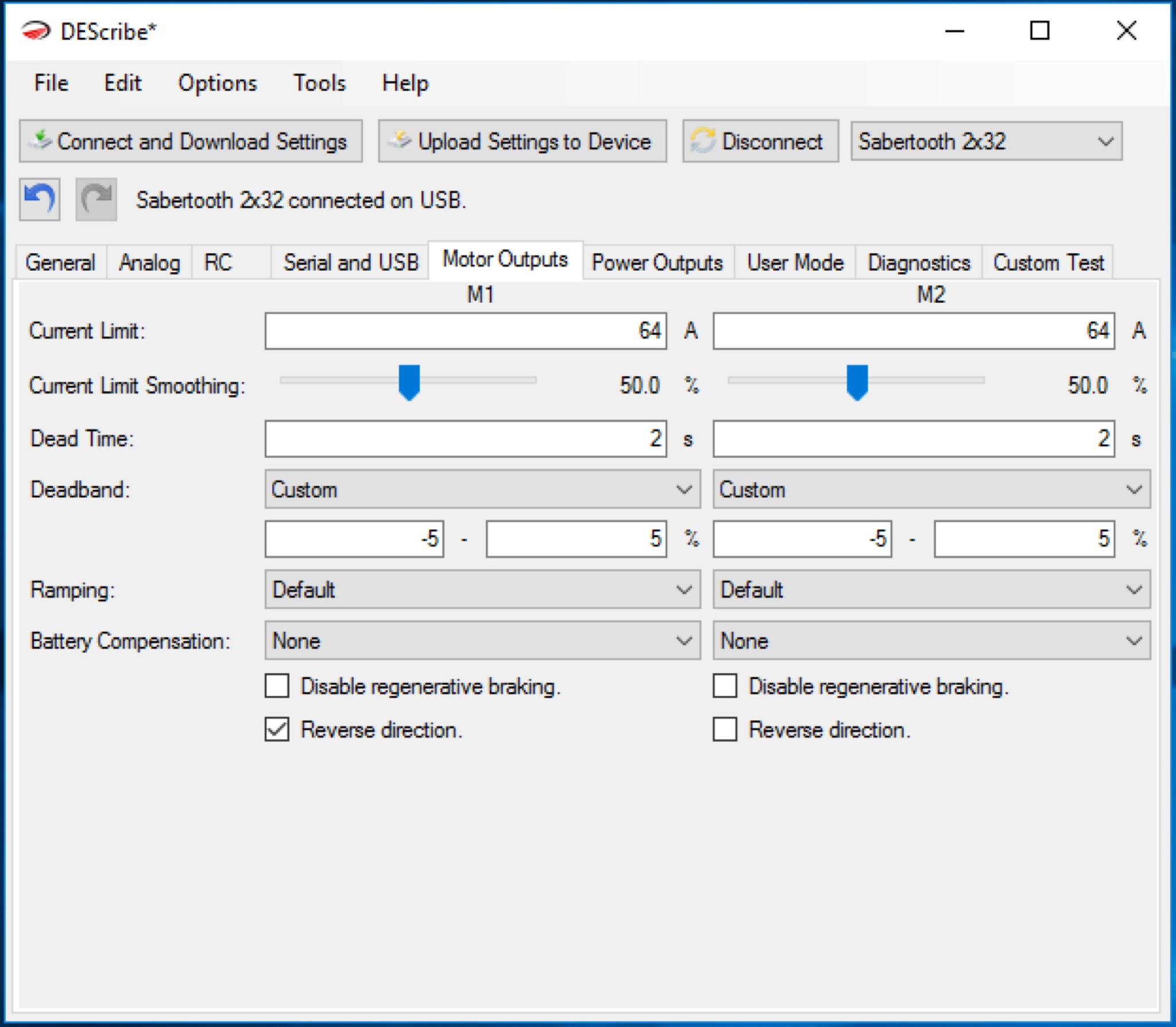
Next up we click on the “Motor Outputs” tab. Notice I set Deadband to +- 5%. I like to have a fairly large zone that the Sabertooth considers as neutral input — otherwise when you stop your robot, if you don’t get the radio controller sticks perfectly centered, you’ll be pushing a tiny bit of current to the motor when you intend for it to be at rest — this isn’t what we want.
You’ll notice that I don’t cover the “User Mode” tab as I’ve never taken time to figure out exactly how to make custom modes work. Perhaps a Dimension rep would point out that my limited gripes could be easily solved by creating a custom “User Mode”.
While we’re speaking of Dimension reps, I have spoken with them (yes, actual people who work at the place where they make the part) in the past and they are refreshingly friendly/helpful/knowledgeable.
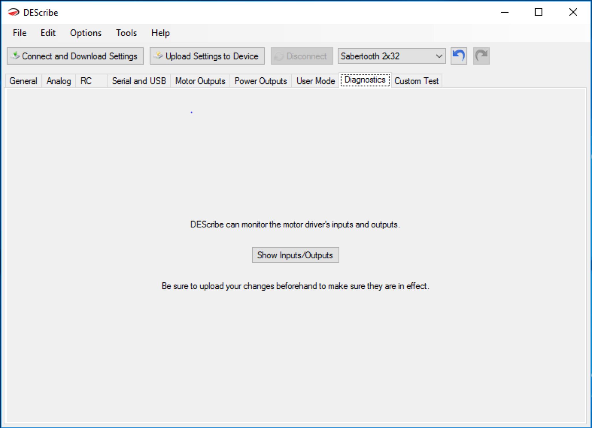
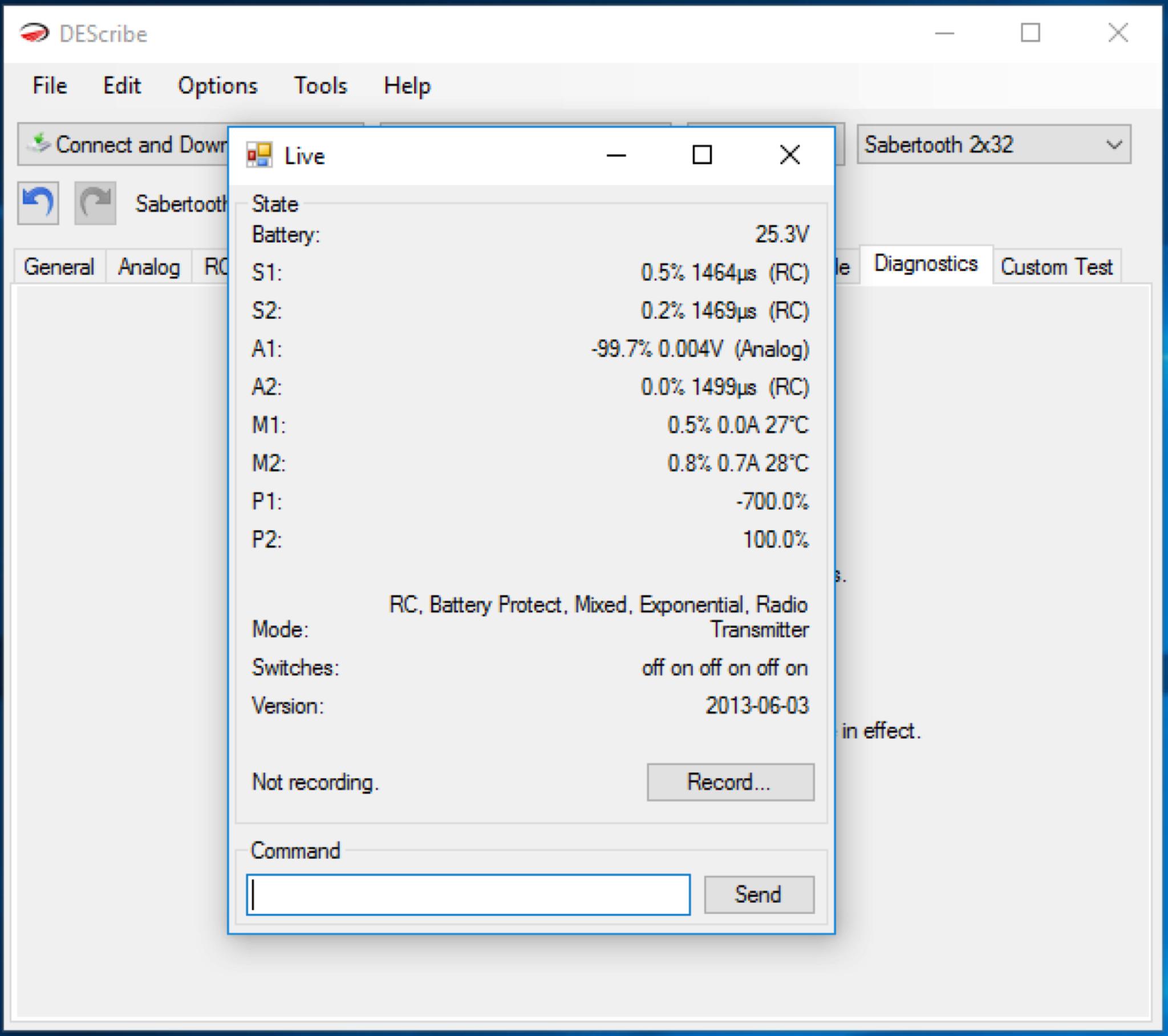
You’ll notice in the “Live” view above that you get an informative peek into the current state of the controller. Of particular interest is the “Record…” button at the bottom. It turns out the Sabertooth allows you to record the controller state during a run for review — this is very handy, in fact, we’re going to explore this a little more in an upcoming post.
Enough talk! Let’s check out a run (that’s little guy laughing in the background):
If you look carefully at the last few seconds of the run above, when Rover 2 crashes down from the last wheelie, it throws off the radio receiver, crashing to a halt. Fortunately the robot escaped harm.
Until next time,
Sincerely yours,
Roby
Notes
- Remember that “M60” is more commonly known as “60A High Power MOS Dual Channel H-bridge DC Motor Driver Module”
- Inquisitive readers may like a picture of the back of the fried M60 for further forensic analysis.
Leave a Reply