
In the last post, we decided to take a small detour away from immediately building big rovers. So today let’s tackle this exercise of creating a small-scale RC-controlled rover as an introduction for future efforts. Since we’re going to be building several rovers on this journey (increasing measurably in size and complexity), it’ll simplify our conversation to give each of them a name. Let’s have an engineer-as-your-marketing-director moment and give it the flashy name of Rover 1.
What parts will we use to build Rover 1, you ask? Here we go…
Bill of Materials
 1. Arduino — First up, you’ll want an Arduino. If you’re reading this blog, you’re likely familiar with this humble, market-creating palm-sized computer. Released in 2006 as a $30 open source single board microcontroller, the Arduino ecosystem has since exploded with dozens of permutations of the small computer, each with various features and form factors. As the Arduino platform has matured, it has significantly lowered the barrier to entry — both in terms of cost and complexity — for interacting with the physical world.
We’ll be using the Arduino UNO R3 — here’s the exact Arduino you see in the pics. You’ll likely be just fine with any Arduino you purchase from a reputable merchant. Current prices on Amazon are around $20 for a genuine board (made by the folks who created the Arduino) or $10 for a knock-off. If you don’t mind waiting for the boat from the Far East, it will only set you back ~$5.
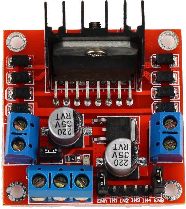 2. L298N Dual Motor Controller — The L298N is a standard cheap solution for controlling two small motors with your Arduino. You can pick it up for around $2 on Aliexpress or get it fast for around $7 via Amazon Prime.
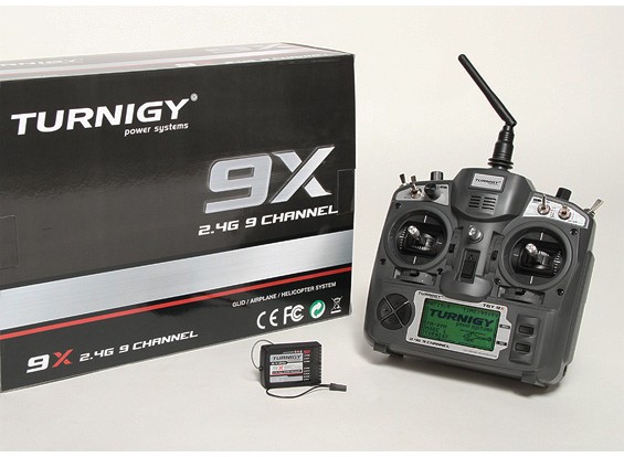 3. Radio Transmitter / Receiver — We’ll use a standard RC radio to control Rover 1. I’ll be using an old Turnigy 9x that was laying around the shop — if you don’t have a radio, you can save cash and should get identical performance from either the FlySky 6 channel or 3 channel radio. If you’re new to robotics, when we talk about the number of channels that a radio has, we’re talking about the number of distinct controls that the radio is capable of transmitting. For Rover 1, we’re using just 2 channels — one for speed and one for steering. Current market prices for the 9/6/3 channel radios are ~ $70/$50/$30, respectively.
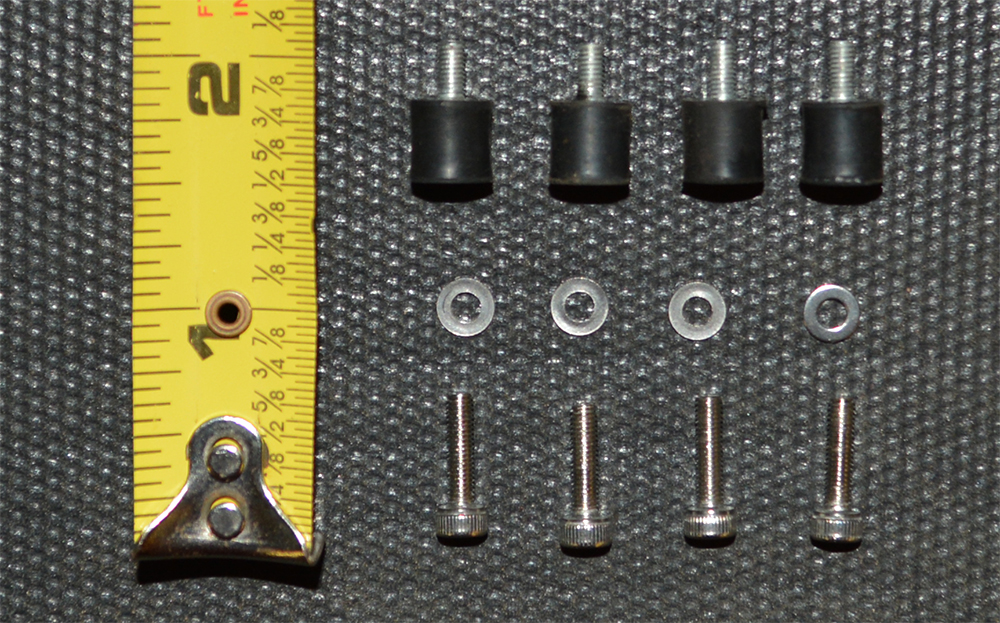 4. Anti-Vibration Mounts — If you’ve ever replaced a car’s radiator, you’re likely familiar with mounting on rubber bushings. With radiators, you’re trying to reduce the vibration to prevent cracking. With autonomous robots, we’re primarily trying to shield the IMU from performance-degrading vibration. Here is a list of mounts on eBay like those we’re using — price-wise, you’re looking at 50 cents a piece. Notice what we use M3 sized stainless hex bolts to bolt through the polycarbonate sheet.
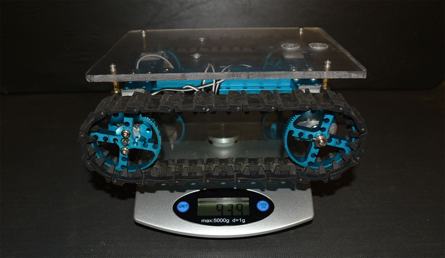
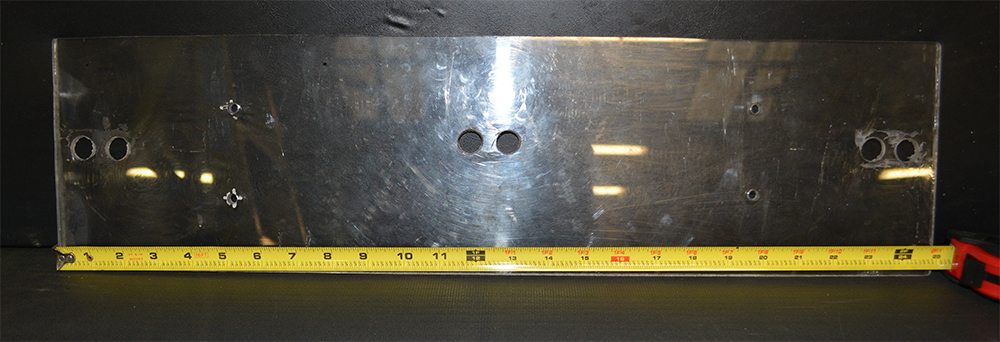 5. Polycarbonate Sheet — For the mounting surface, we cut up an old sheet of .25″(6.4mm) polycarbonate to 8.5″ x 6.5″ (216mm x 165mm). The main non-obvious consideration for your mounting surface is to choose something non-magnetic. If it’s magnetic, you don’t want it close to a compass. Aluminum is great, stainless steel (i.e. Type 316) may work, but keep in mind that not all stainless steel is non-magnetic. You can pick up a sheet of polycarbonate like we used on eBay for around $10. If you order a big sheet or higher quantity, you’ll drive down that cost per unit considerably.
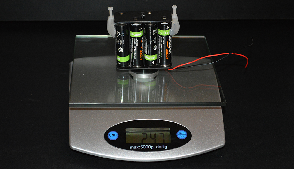 6. NiMh (Eneloop) Batteries — There are far better batteries if you’re seeking an optimal power-to-weight ratio. If you don’t have a set of AA NiMh batteries laying around, you won’t regret springing for the purchase. If you’re still using AA/AAA alkaline batteries for high-drain devices and throwing them away, it’s time to step into the light of good rechargeable batteries. Check the reviews: NiMh rechargeable batteries are NOT the old school rechargeable batteries that died quickly, had “memory” issues, and were a general thorn to enjoying life. NiMh batteries work fine in this application because Rover 1 won’t draw much current — it won’t be winning any races. As far as which brand to use — I’ve had good luck with both Amazon Basics and Eneloop. You can pick up a NiMh AA 8 pack for around $15. You’ll also need an NiMh charger — spring $10 and you’ll land a cheap one that should work fine.
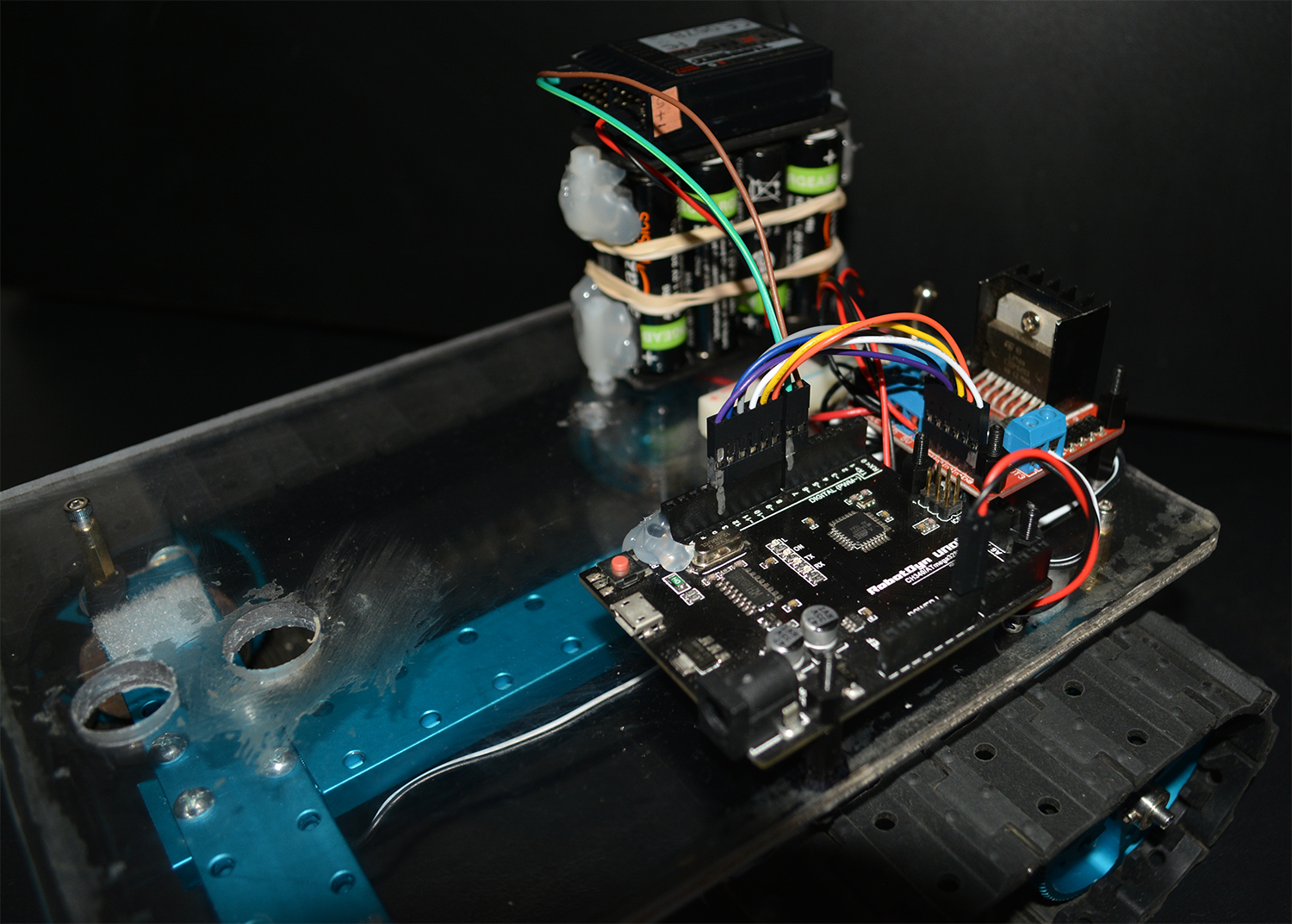
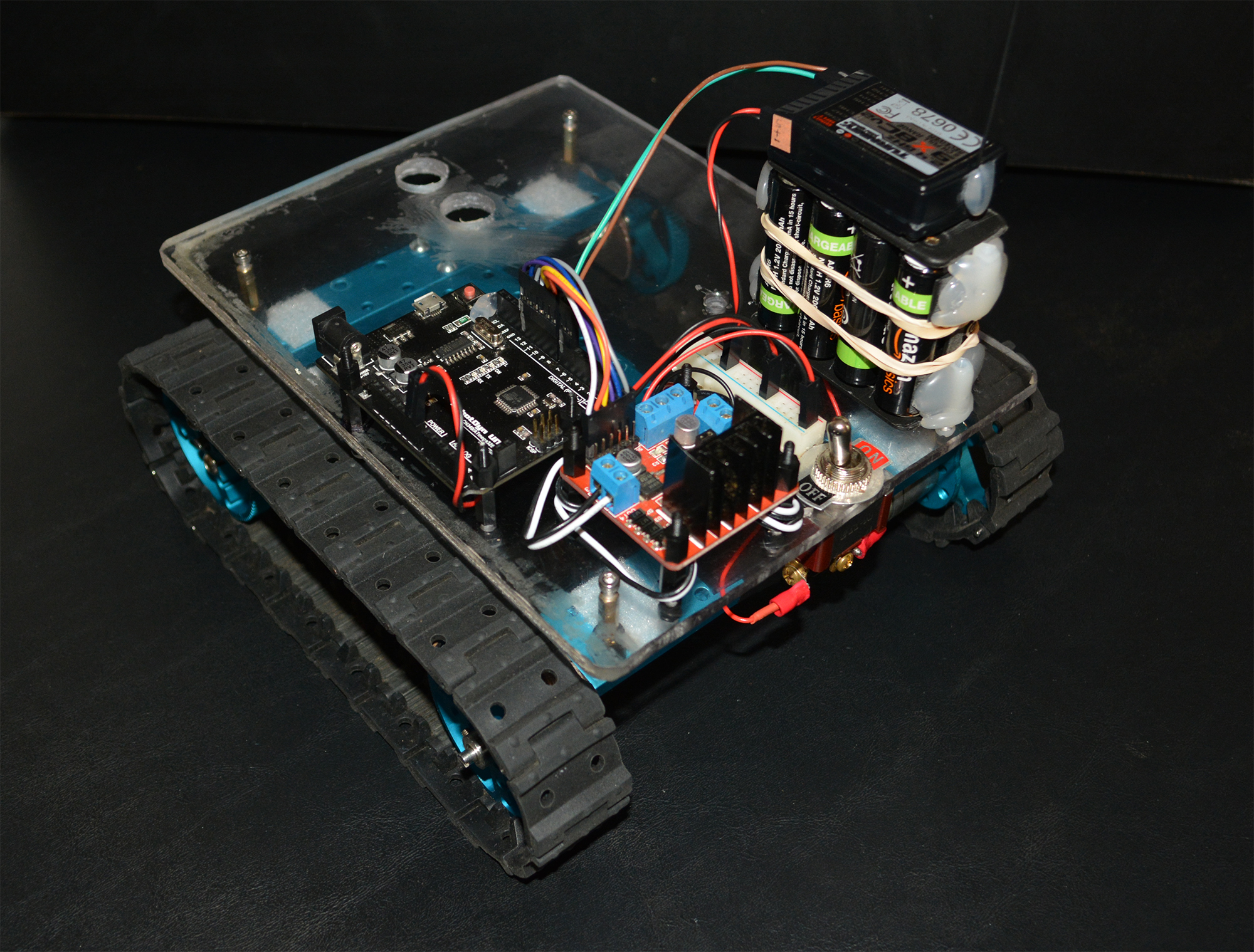
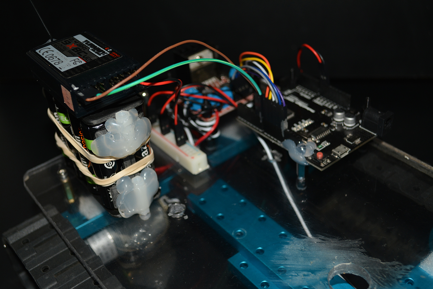
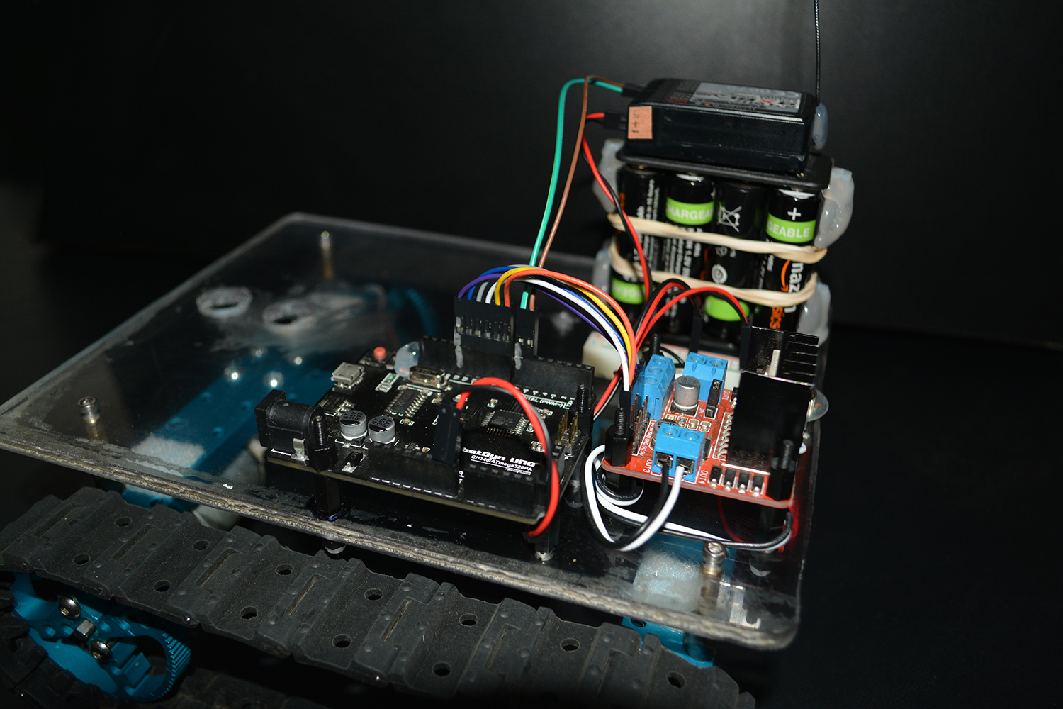
7. Eight Place Battery Holder — We’ll use a generic battery holder that can you buy for around $2. This holder connects all 8 batteries in series. Note that NiMh batteries are rated at 1.2v instead of the traditional 1.5v. So the voltage for our battery pack is 8 x 1.2v = 9.6 volts. Notice in the picture above that we hot glue a threaded nylon spacer to either side of the batter pack. This will make mounting the battery pack super easy.
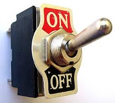 8. On-Off switch — We use the fancy Eaton switch. Really these are commodity items and you can grab a cheap 5 pack of generic heavy duty switches for under $5. I highly prefer this old-school metal switch to the new-fangled plastic switches.
9. Wires — I like to make my own wires & connectors to keep things looking clean, but if you’re wanting to get started quickly, Amazon will happily rush you a pack of breadboard wires for $8.
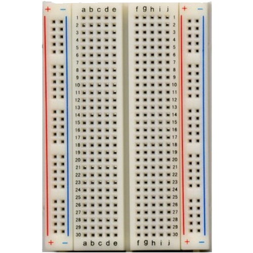 10. Breadboard — You’ll notice in the Rover 1 pictures that I ripped the power rail off a breadboard and created a long 5v power supply. These breadboards only cost a few bucks and are wonderfully handy when you’re experimenting with electronics.
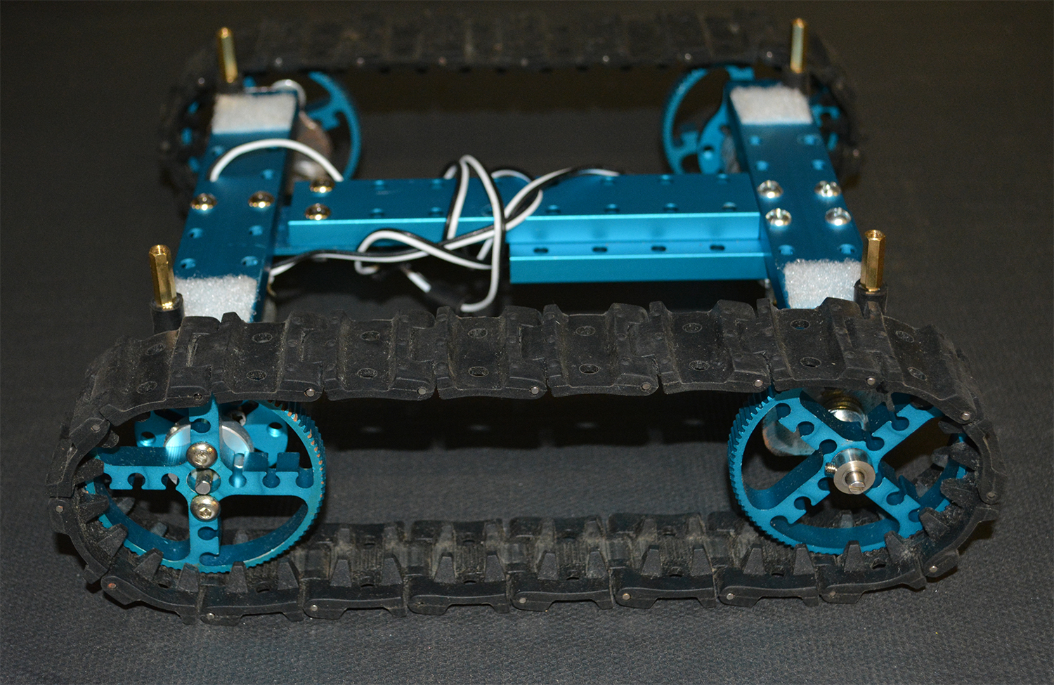
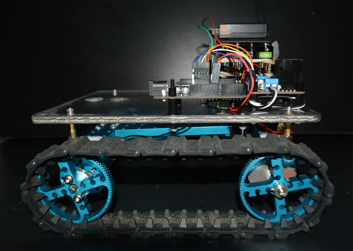
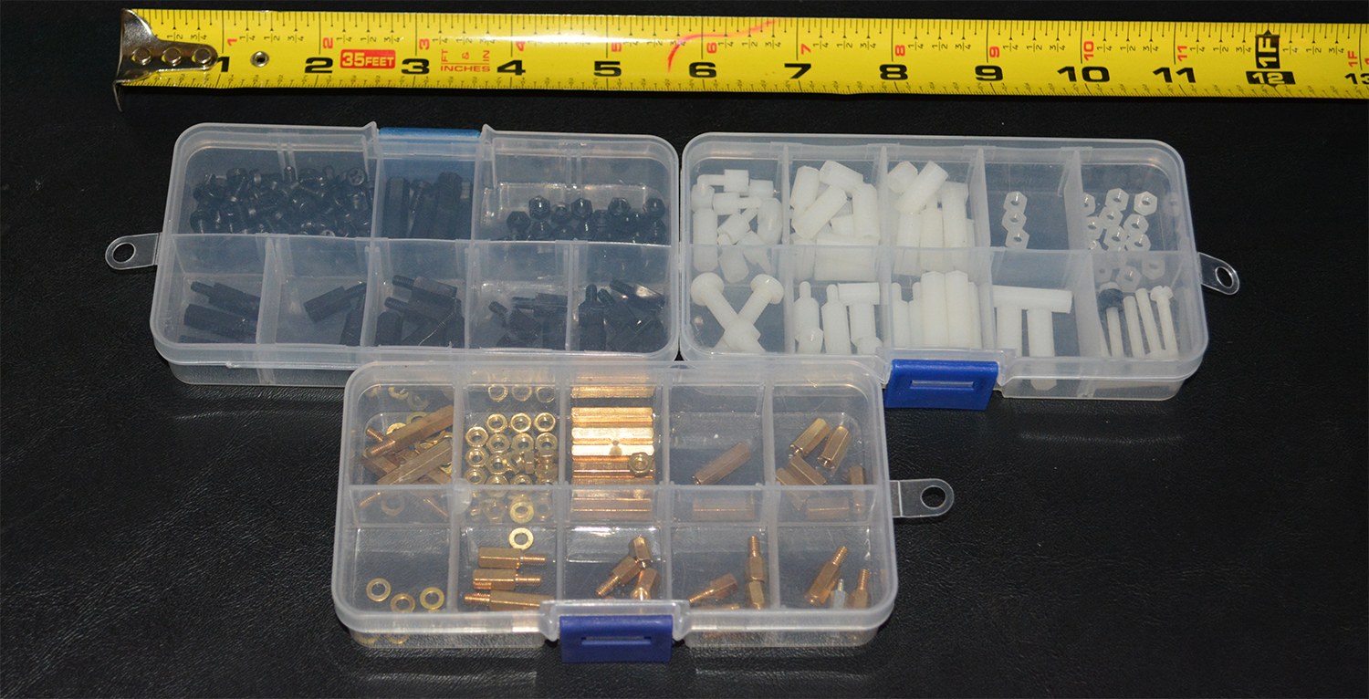 11. Brass & Plastic Spacer/Standoff — We use spacers (or “standoffs”) to elevate the polycarbonate platform above the rubber tracks and to mount/elevate the electronic boards above the polycarbonate platform. These little spacers are incredibly useful and they won’t set you back much cash.
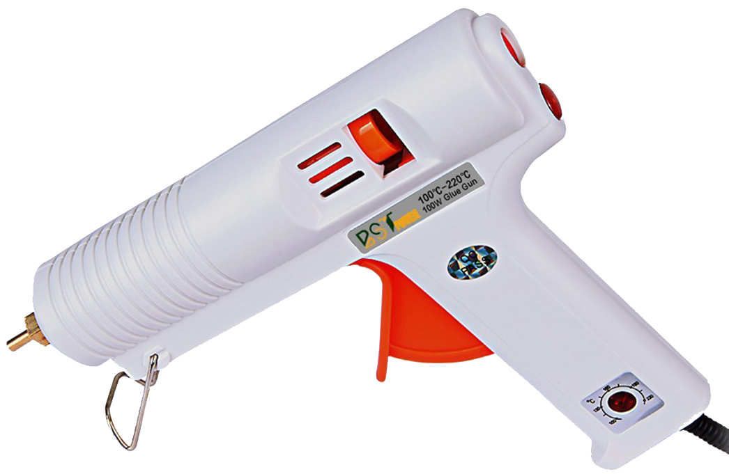 12. Hot Glue — If you’re an aspiring roboticist and you don’t have a hot-glue gun in your arsenal, then you’re likely losing considerable time. Hot glue is the Duct Tape of Robotics. Hot glue is strong, flexible, bonds to many surfaces (sans metal or anything really slick/shiny) — but most importantly, it’s FAST. When you’re doing a rapid prototype, you can’t wait around for 45 minutes for glue to dry. I buy hot glue sticks in bulk from this vendor.
I think that’s an exhaustive list of the materials we’ll use to build Rover 1. Now let’s look at putting it all together.
Building Rover 1
Let’s go through a photo-montage showing Rover 1 as it progresses through assembly:
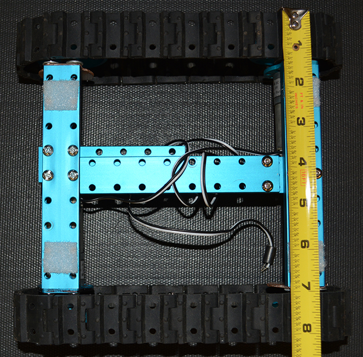
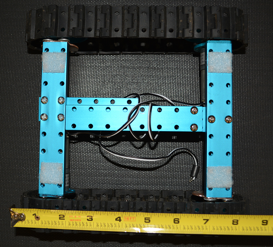


Assembly Notes
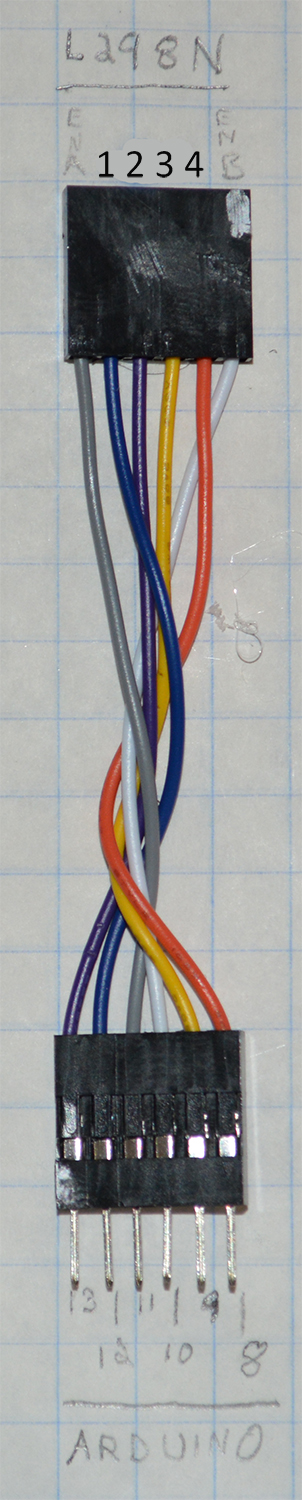
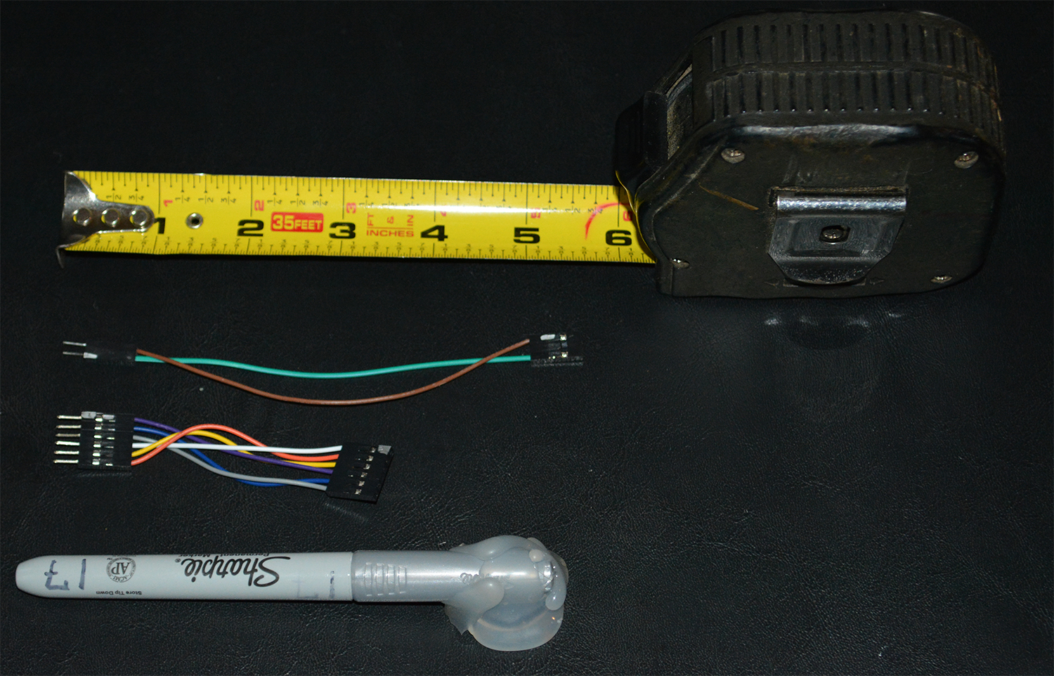
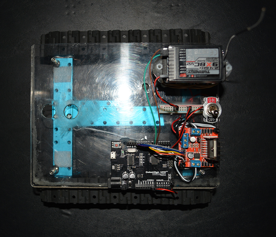
I hope the pictures above help answer most questions you might have about how the rover was wired up. Looking back over the pictures, I suspect you may have some questions about the 6-wire harness that connects the Arduino to the L298N.
I took a picture of the harness and labeled the wires on both ends. Notice in the picture of the harness on the left that the top is the L298N end. So, for instance, the gray wire on top left connects the L298N ENA pin to the Arduino 11 pin. The blue wire on the top left connects L298N Pin 1 to Arduino Pin 12, and so on.
You don’t need a custom wiring harness like this — you can do just fine with the breadboard wires mentioned in the BOM section above. You only need to connect the appropriate Arduino pins to their counterpart on the L298N per the diagram on the left.
Notice in the pictures above that we used brown and green wires to connect channel 1 and channel 3 from the receiver to the Arduino pin 6 and pin 7, respectively.
On my Turnigy 9x transmitter, the left stick is mapped to speed (channel 3) and the right stick is mapped to steering (channel 1). That’s a fairly common mapping, but you’ll want to ensure that your transmitter is mapped accordingly. Specifically, whatever channel you’ve assigned to speed must connect to Arduino pin 7 and whatever channel you’ve assigned to steering must connect to Arduino pin 6.
Wrapping Up
That was a fair amount of work! Let’s save the really fun part — the Arduino code — for the next post.
If you guys are new to programming, if you’ve been afraid to start programming, or perhaps if you’ve tried a little programming and it didn’t quite gel, I hope you’ll gather your courage and dig in next time we meet.
Until then, Peace my fellow roboticists.
Sincerely,
Roby
7 Responses
Hi Roby
I recently bought the 100a version of this Chinese built controller to power a electric zero turn lawn mower that I am dreaming of building! I came across this blog while searching for information on how to operate the controller.
My intent is to build a ride-on type mower that is controlled, preferably with a single joystick, but possibly with two controls with tank type steering. I will be using two 24v 15 amp wheelchair motors that I scored from the dump!
The reason I went with the 100a controller is that I want to run the whole contraption on 36v because I have a 42″ Electak mower deck that has 3 36v motors that I will be using, (I have the whole Electrak tractor that was built in 1973 and currently us it to cut my lawn) What would be the simplest way to control this controller directly with a joystick? I can see myself sometime in the future going down the road of autonomous control but right now I don’t mind riding on it so using a rc transmitter and receiver seems more complicated than it need to be! ( I do have the arduino and a few RC controllers for future consideration)
Ed,
Did you see the article comparing the M60/M100 with the Sabertooth? Gist: get the Sabertooth unless you’ve got a lot of time to spend on the driver.
Good luck with your project — hope you blog about it if you get rolling — it sounds like fun.
–Roby
Time is no issue for me ( I’m retired and love tinkering) I’d have got the sabertooth if I’d known about it before I ordered the M100. Think I’ll leave off buying the sabertooth till I get frustrated with the cheap one! I know how to get arduino to run it but I haven’t found a joystick that I like . The little one usually used looks so puny to run a real machine! I’m using fortress scientific motors
Can the “m60” be controlled with a simple joystick without the complication of an Arduino for a ride-on vehicle?
Hi Ed,
I haven’t tried — the Sabertooth controller performs so well that I’d have trouble spending much time on the “M60”.
–Roby
Hi there,
I am wondering where have you got those tracks and sprockets?
I was looking for such solution, but everything I have found was superdroidrobots track system which is costly. Another Lynxmotion track system is not suitable for outside use.
Hi Vaidas,
The tracks are from an educational robotics kit by Makeblock — a little more color in this article.
Don’t plan on using that kit for any serious work though — it’s great for learning but not robust for outdoor use.
Best wishes in your adventures!
–Roby