We’ve had some fun hacking together autonomous mowers powered by cheap electric wheelchair powertrains obtained on the flooded-by-govt-subsidies second hand market — but the autopilot related technology available in 2019 enables us to achieve much more.
Exhibit A:
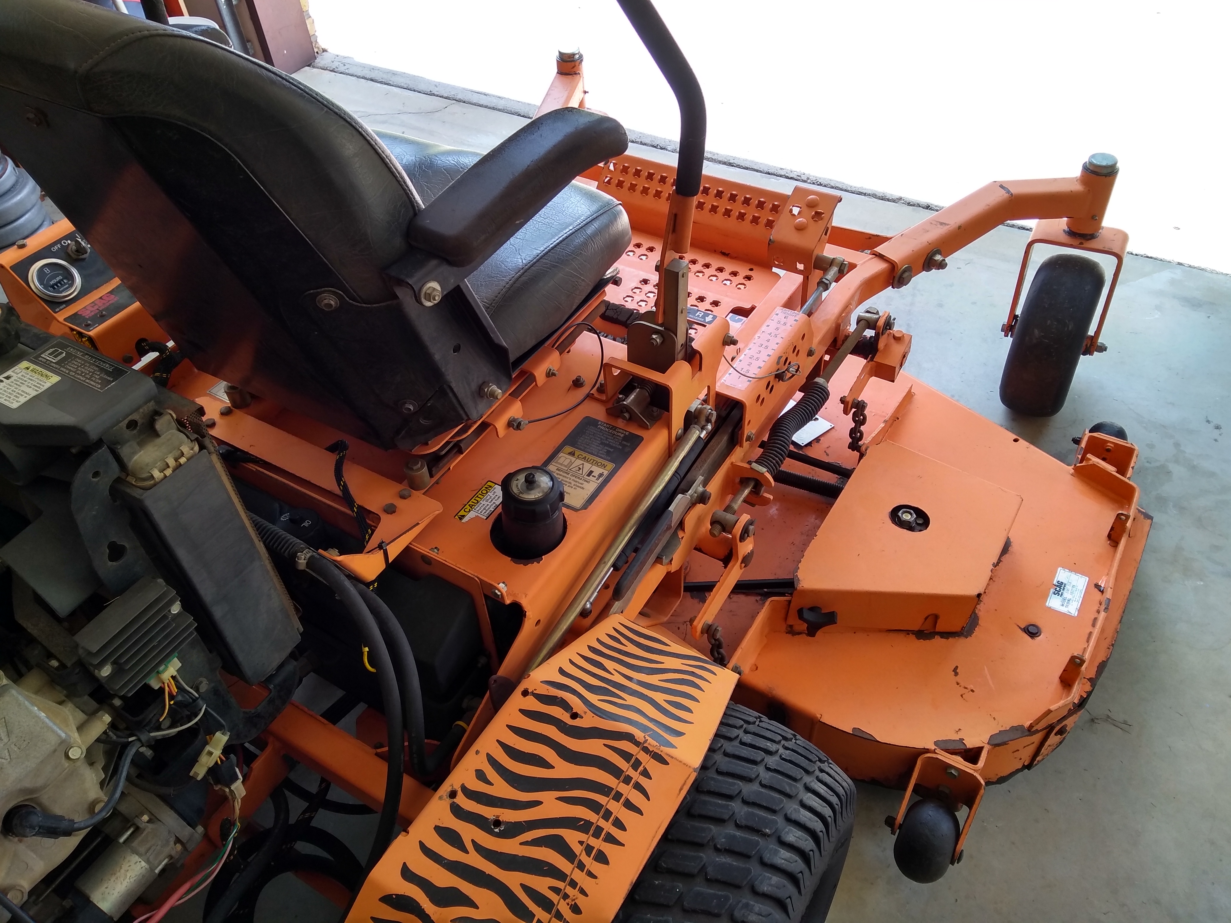
That’s a timelapse of a Scag (the dominant heavy-duty commercial mower brand in my corner of the world) 72″ Turf Tiger skid-steer mower mowing over some old gentle farm terraces next to our grass runway. The mower is running at approximately 3.8 miles per hour (1.7 meters per second).
This run (and many more) was achieved without any human intervention — but you’ll notice that I follow it carefully and monitor the behavior as this was an early run with the particular build / configuration.
Lofty Goal & Cordial Invitation to You
The goal of this article is to clearly present the components of that mower for your consideration. As usual, if I forget something (as is usually always the case) — please drop a line in the comments and I’ll try to color in whatever seems vague. I really do appreciate all the comments and questions that readers have submitted on these posts over the last couple of years — when I first made the leap from a software-centric world to robotics world there were so many fire hydrants of information from so many engineering disciplines that it felt like I was underwater for years. Humans aren’t born possessing much of even the basic knowledge that underpins all of robotics — most eager novice robot builders first encountering 5v, GND, VCC sockets on an expensive board will be massively nervous about committing to what they assume those letters mean — and perhaps they’ll utter a silent prayer hoping that the board doesn’t smoke and simmer when they make the leap and plug in their breadboard wires. In other words: if you have a question about the project (even if it seems much more “elementary” than whatever other comments are being made), please don’t hesitate to log the question — you can just use a throwaway account if you want to wait until you’re some kind of robot ninja to disclose your identity to the world.
Warning! This article describes the process of building an autonomous lawn mower for your entertainment and scientific inquiry. THIS IS NOT AN INSTRUCTION MANUAL OR GUIDE FOR BUILDING AUTONOMOUS MOWERS. IF YOU DECIDE TO BUILD ANYTHING YOU ARE DOING SO AT YOUR OWN RISK. This is a VERY DANGEROUS machine — please consider carefully the implications before even thinking about building a machine like this. If you plan on building a self-driving mower you are doing so at your own risk.
Additionally, ArduPilot’s Developer Code of Conduct explicitly excludes ArduPilot from running systems where ArduPilot is effectively in control of human lives.
How the Build Went Down
The electronic footprint we added to the big Scag automower is very similar to the smaller automowing rig we’ve previously discussed. The points of dissimilarity between these mowers proved to be some of the places that required the most creativity — most notably being selecting and implementing the servos (i.e. the motor/shaft apparatus that pushes the mower handlebars back and forth).
The Quest for the Perfect Servo (or “An Ode to Pops and Wingxine”)
You are likely familiar with skid-steer mowers, but if not, here’s what happens — you’ve got 2 handles — one for your right hand and the other for your left hand — when you push the right handle forward of neutral, it makes the right wheel go forward (the further you push it forward, the faster the wheel goes) — when you pull it back behind neutral it makes the right wheel go backwards (the further you pull it back the faster the wheel goes). Same logic for the left handle and the left wheel. So, the idea of a skid-steer vehicle is that you’ve got 2 inputs that have an identical bearing on both speed and direction (as opposed to a traditional vehicle where 1 input (the gas pedal) has the biggest impact on speed and the other input (the steering wheel) largely determines direction).
Our challenge is to come up with some mechanical component to attach to either handle and then to configure that component to work nicely with our autopilot.
I have one chief requirement for the servos that control the drive arms: the servos must be overridable by an average-strength person in any reasonably imaginable scenario.
Pioneering Efforts
Way back in 2005 a couple of highly talented engineers published a paper giving an overview of how they had equipped a Scag Turf Tiger with radio control in support of government rollover testing.

The craftsmanship those guys showed in that conversion was impressive, and their design apparently met the government rollover testing needs perfectly — but they chose linear actuators to move the drive arms and this is not appropriate for robots that are operating in the presence of humans[1].
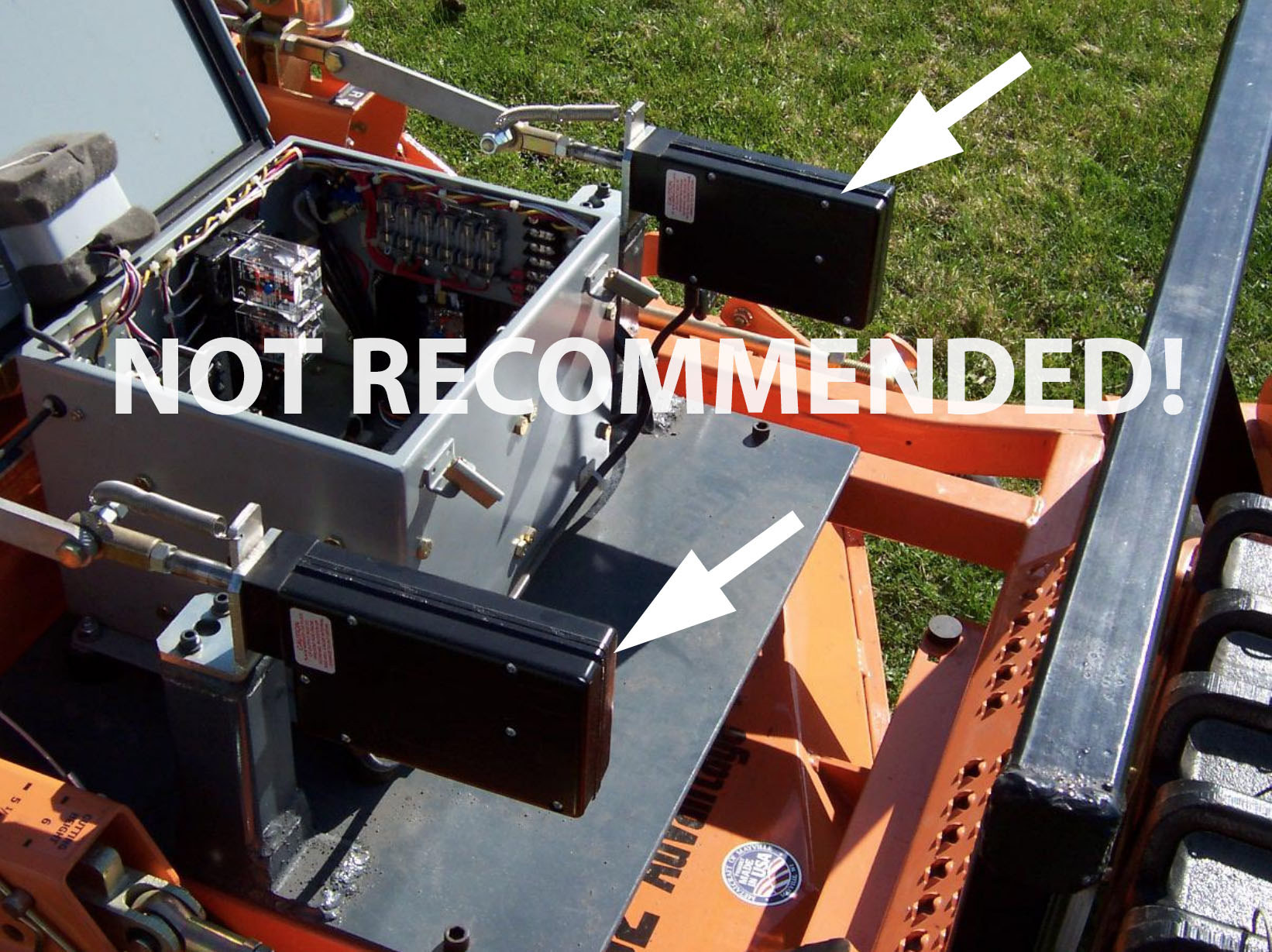
Linear actuators typically have a high static (holding) load rating — so when you cut power to the actuator (or attempt to override it when it is powered) the actuator is incredibly difficult to override. Working around 1500 pound blade-slinging autonomous machines is stressful enough without the thought that I can’t manually override the control arms.
But if we just throw out linear actuators on safety grounds (assuming your robot will ever be around people) and convenience/practicality grounds (I want to effortlessly drive the big Scag around with the autopilot turned off without unhooking the servos from the control arms), what other option do we have for controlling the arms?
In order to answer that question, I’ll need introduce you to two folks: Wingxine and Pops.

Who is Wingxine?
The identity of Wingxine is largely shrouded in mystery, but this enigmatic genius in the Far East has secured entry into the Huge Skid-Steer Robot Hall of Fame by making and then delivering upon the following observation:

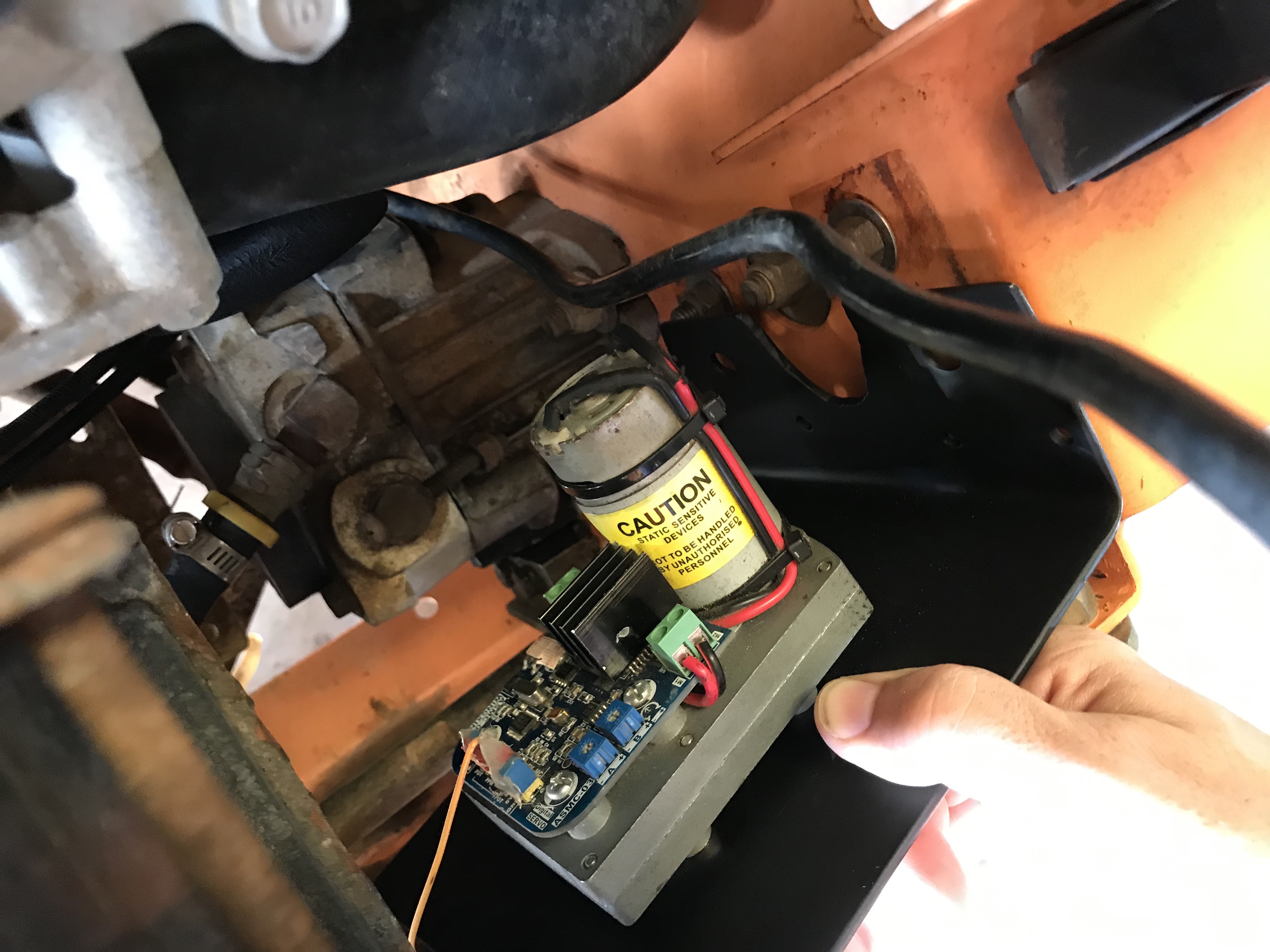
Wingxine’s moment of robotics glory arrived as she or he realized that if you mount an H Bridge motor driver on a cheap-reliable-torquey-proven-ubiquitous TAKANAWA 555 Metal Gear Motor that you’ve just minted some legit servo Graphene from readily available components.
If you spend much time sourcing robot parts from folks on the other side of the globe, you’ll eventually run across a few who simply stand out in terms of the quality of components they consistently create and deliver. Wingxine is precisely that kind of individual: you are strongly advised to check out his/her eBay presence and AliExpress store.
Mower Control Arm Servo Overview
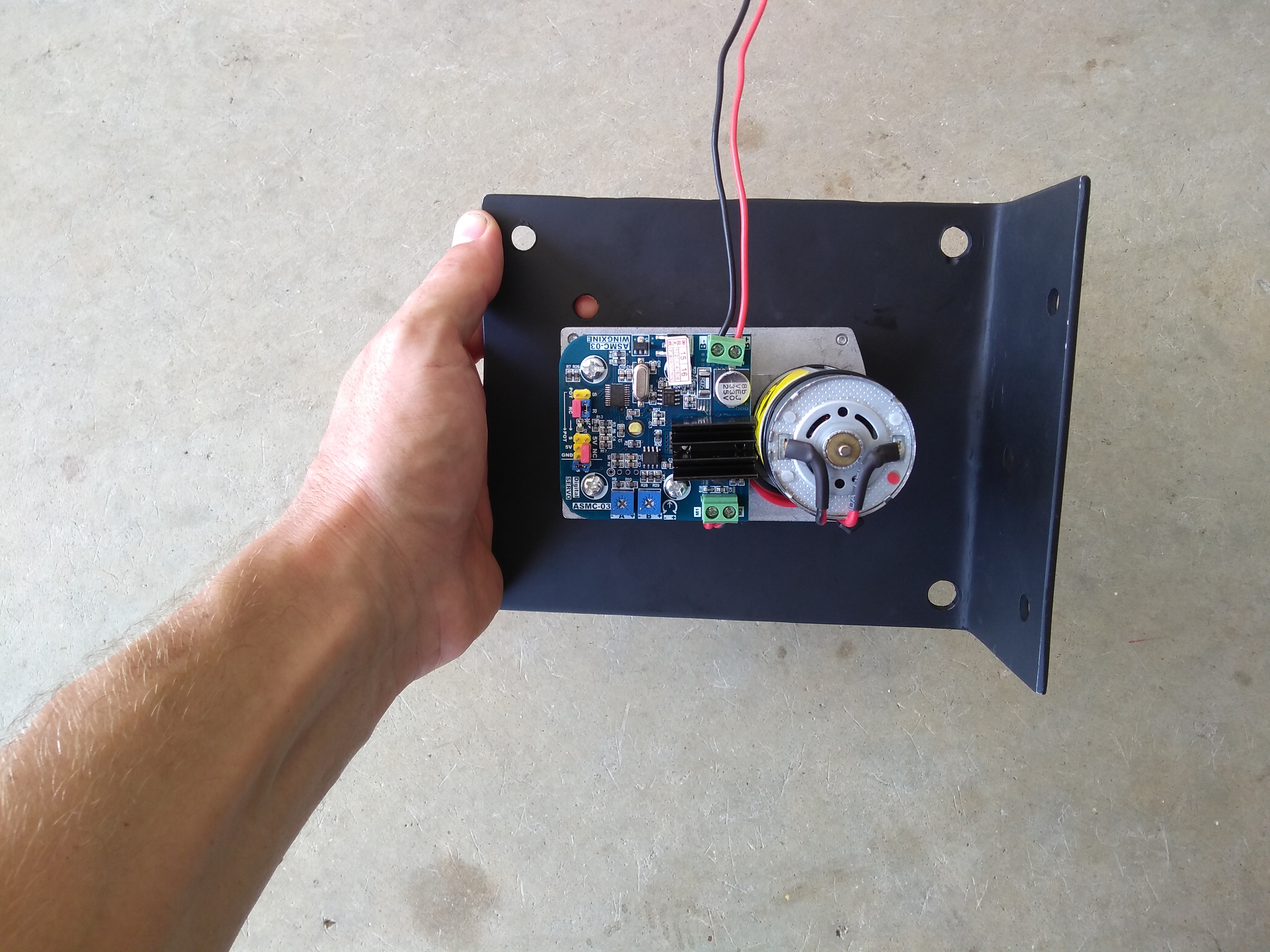
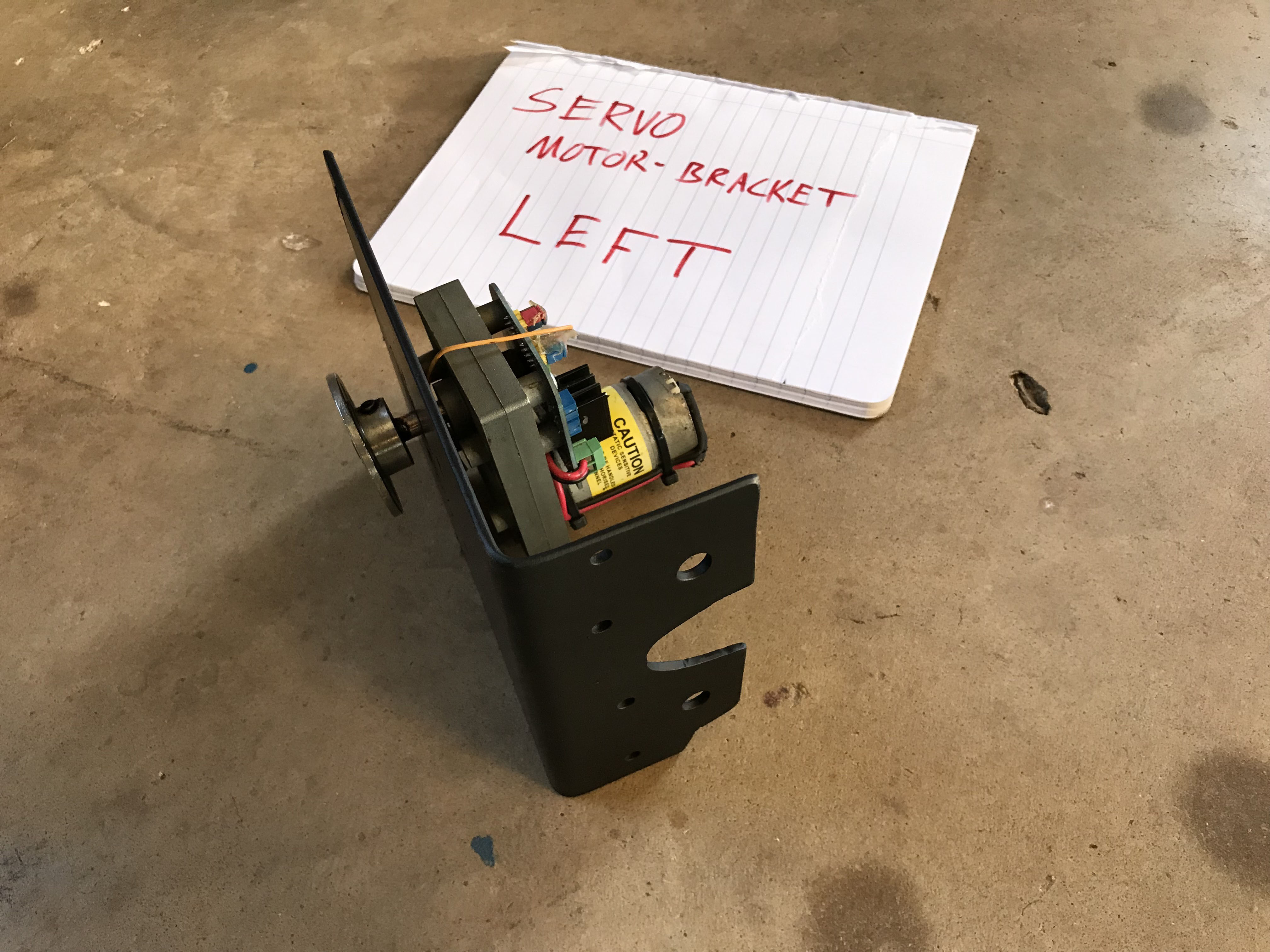
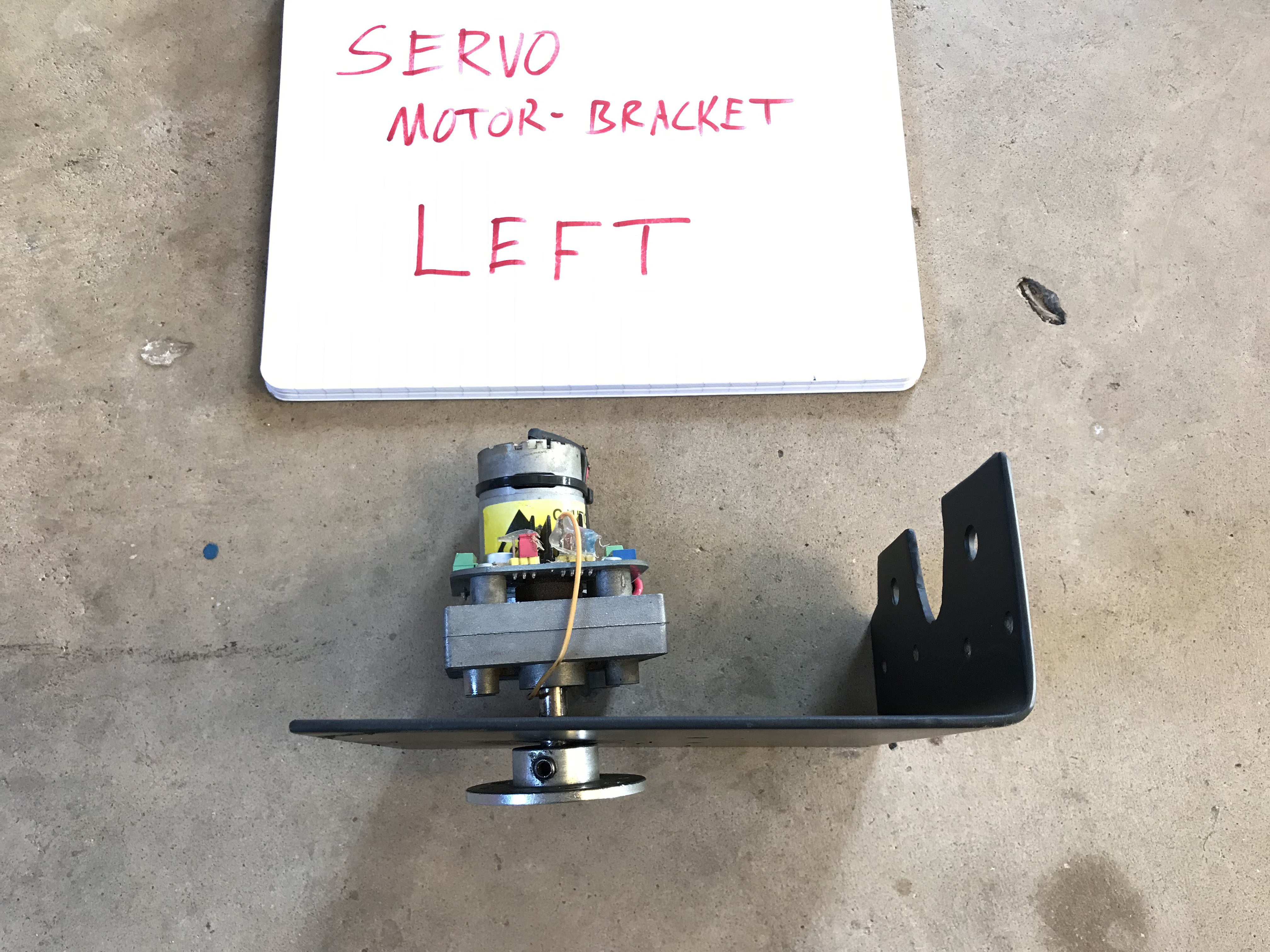
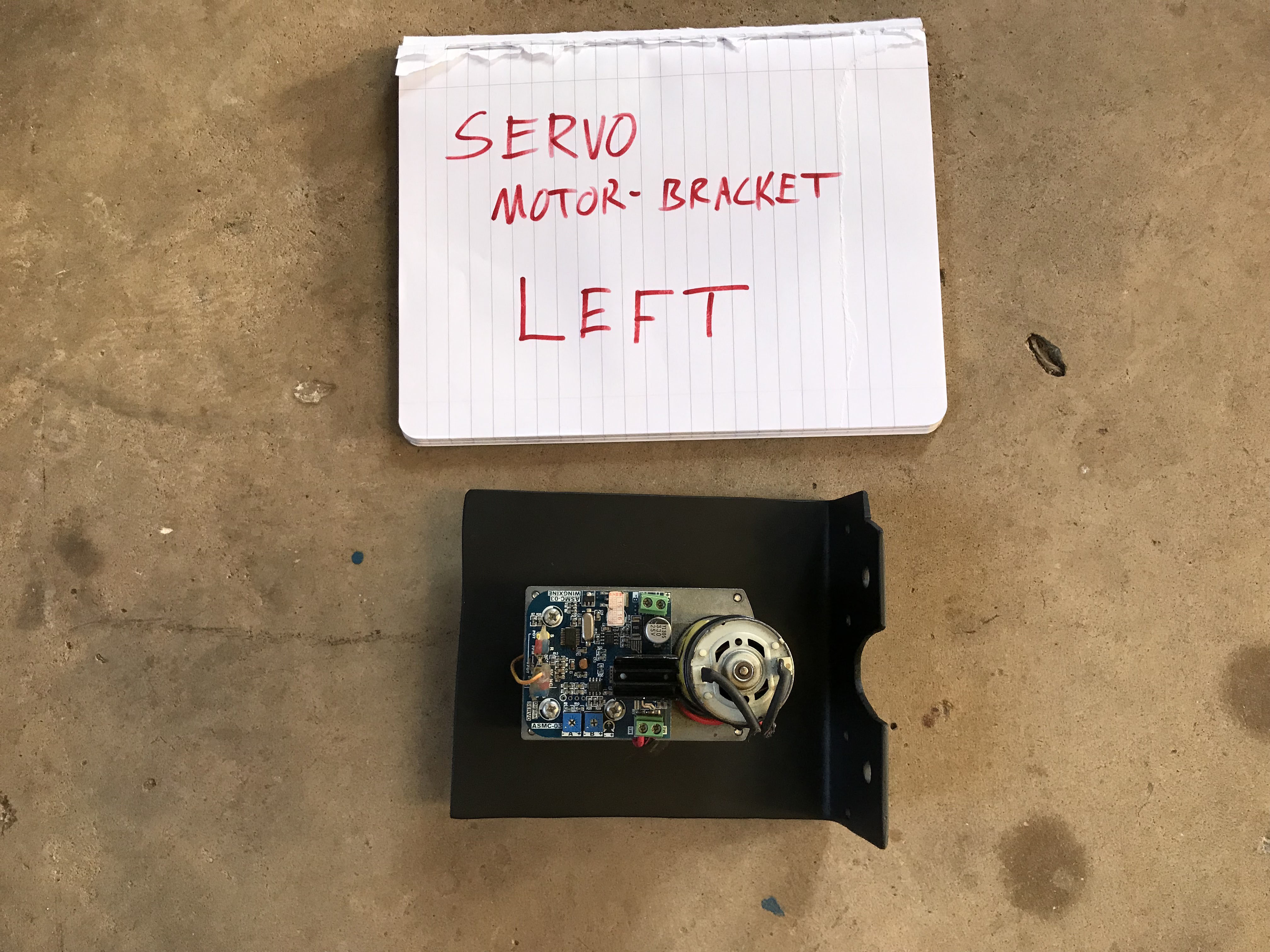
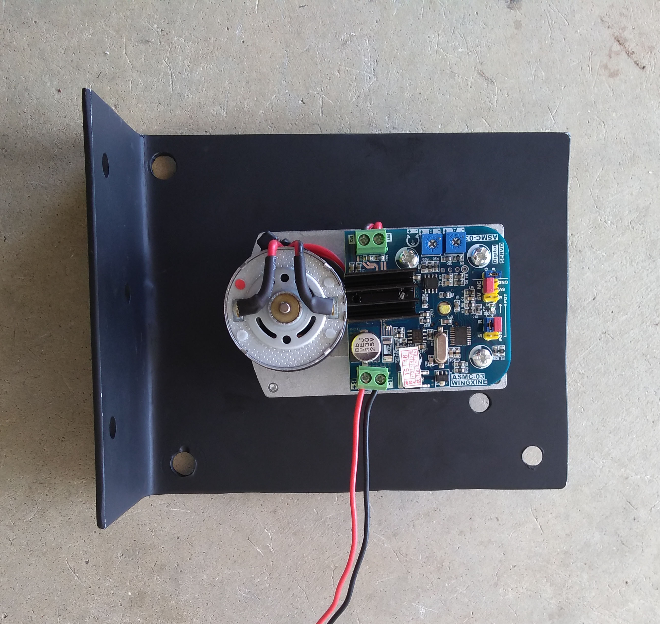
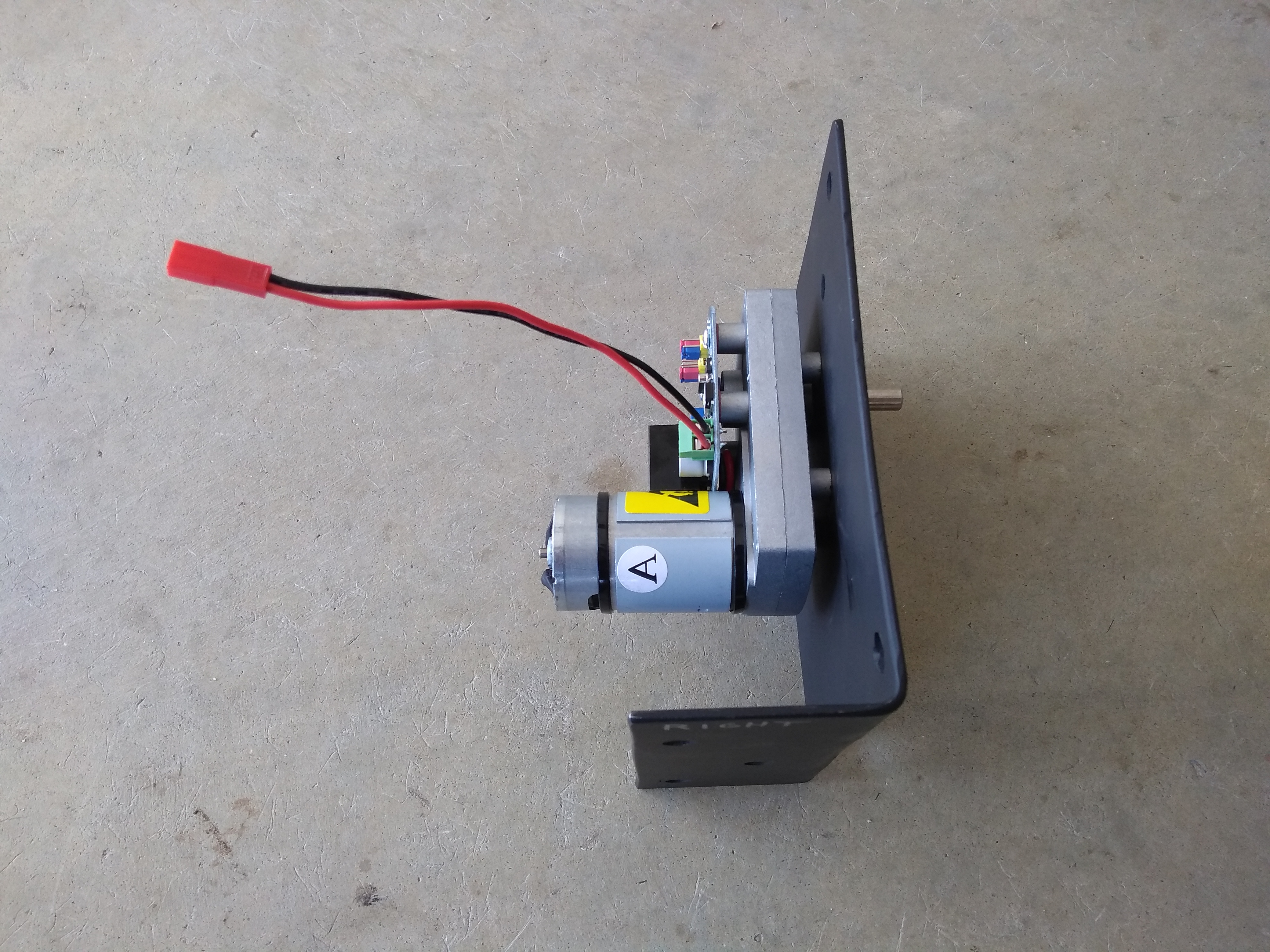
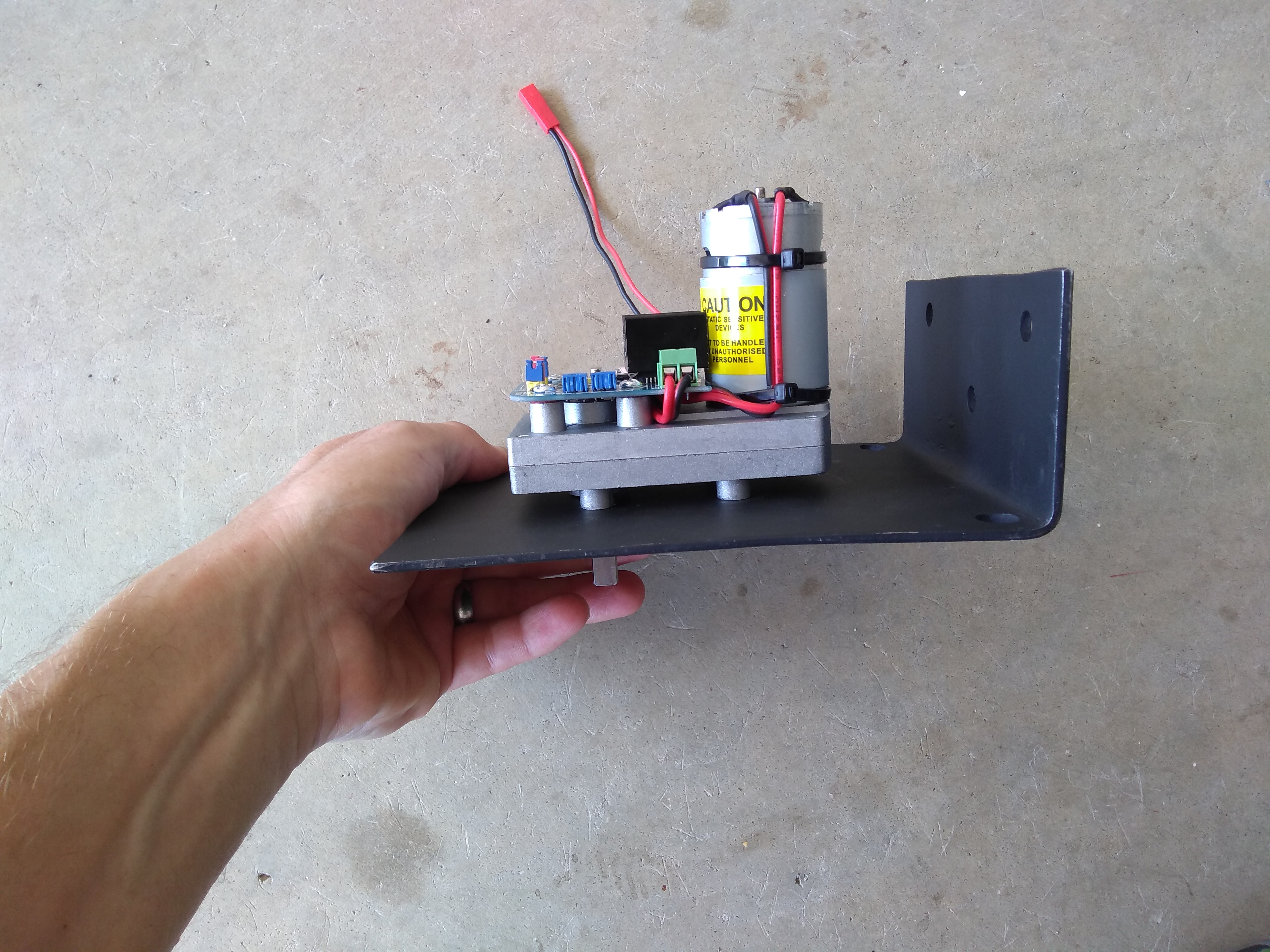
The specific servos we’re using to drive the big Scag mower are two Wingxine ASMC-03A servos:

Note that the ASMC-03 servo is now deprecated in favor of the newer ASMC-04, and you can pick it up in either the ASMC-04A or ASMC-04B flavor.
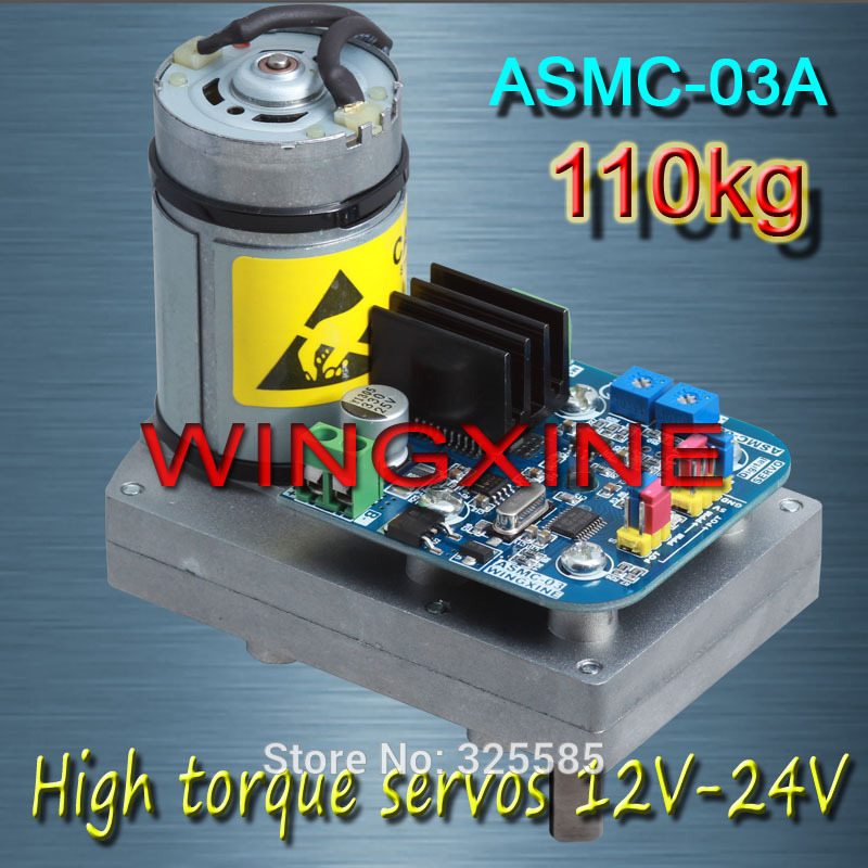


Seeing that the ASMC-03A is deprecated, I went ahead and attached all the stock documentation above (largely for selfish reasons) because this stuff sometimes has a way of vanishing from the internet[2] (and we still have a dozen or so of these servos laying around the shop).
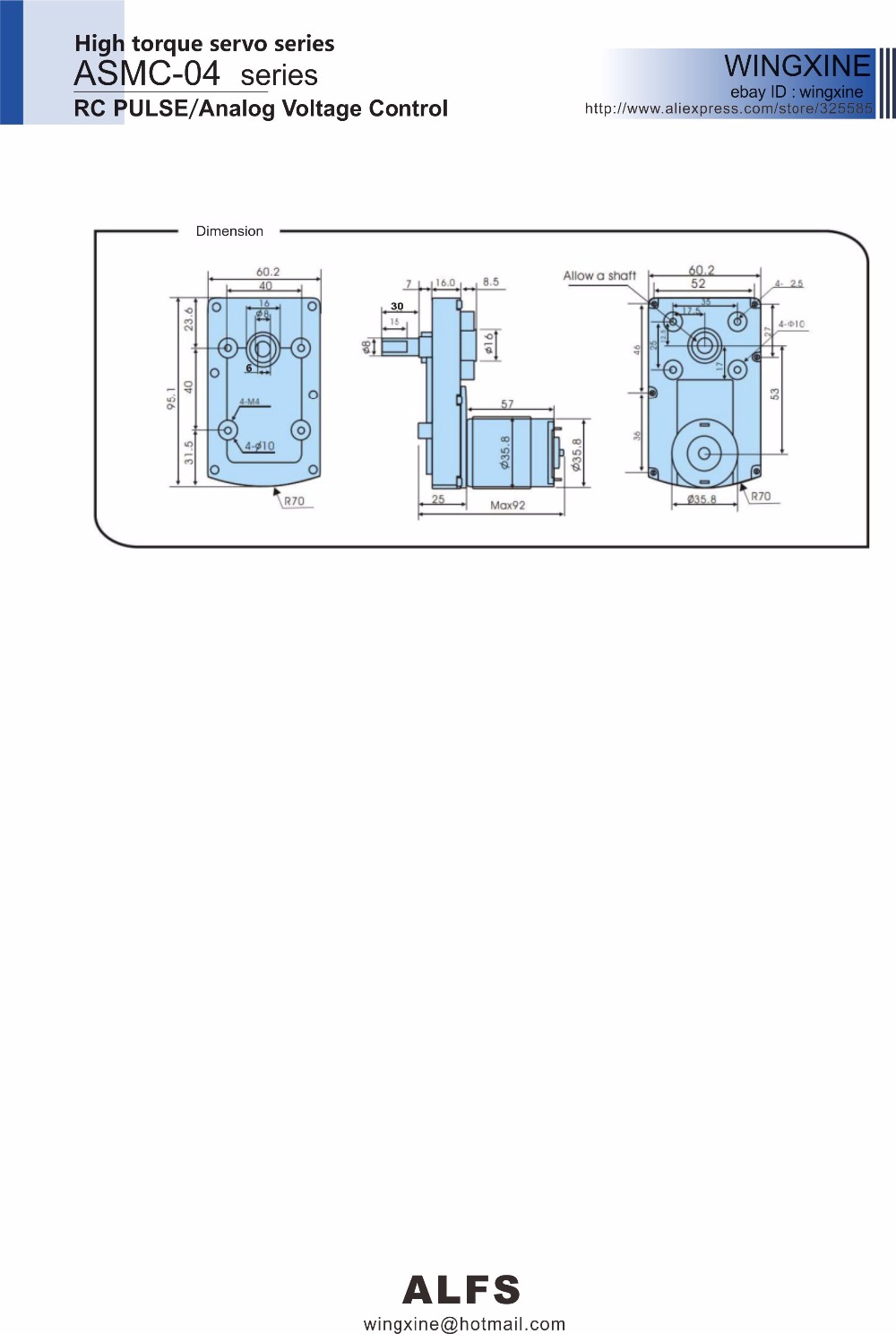
Since the ASMC-04A is the standard going forward, let’s go ahead and grab those docs too:
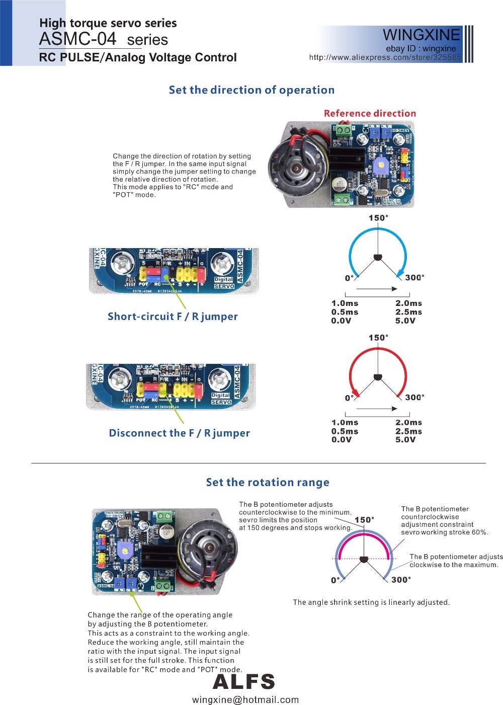


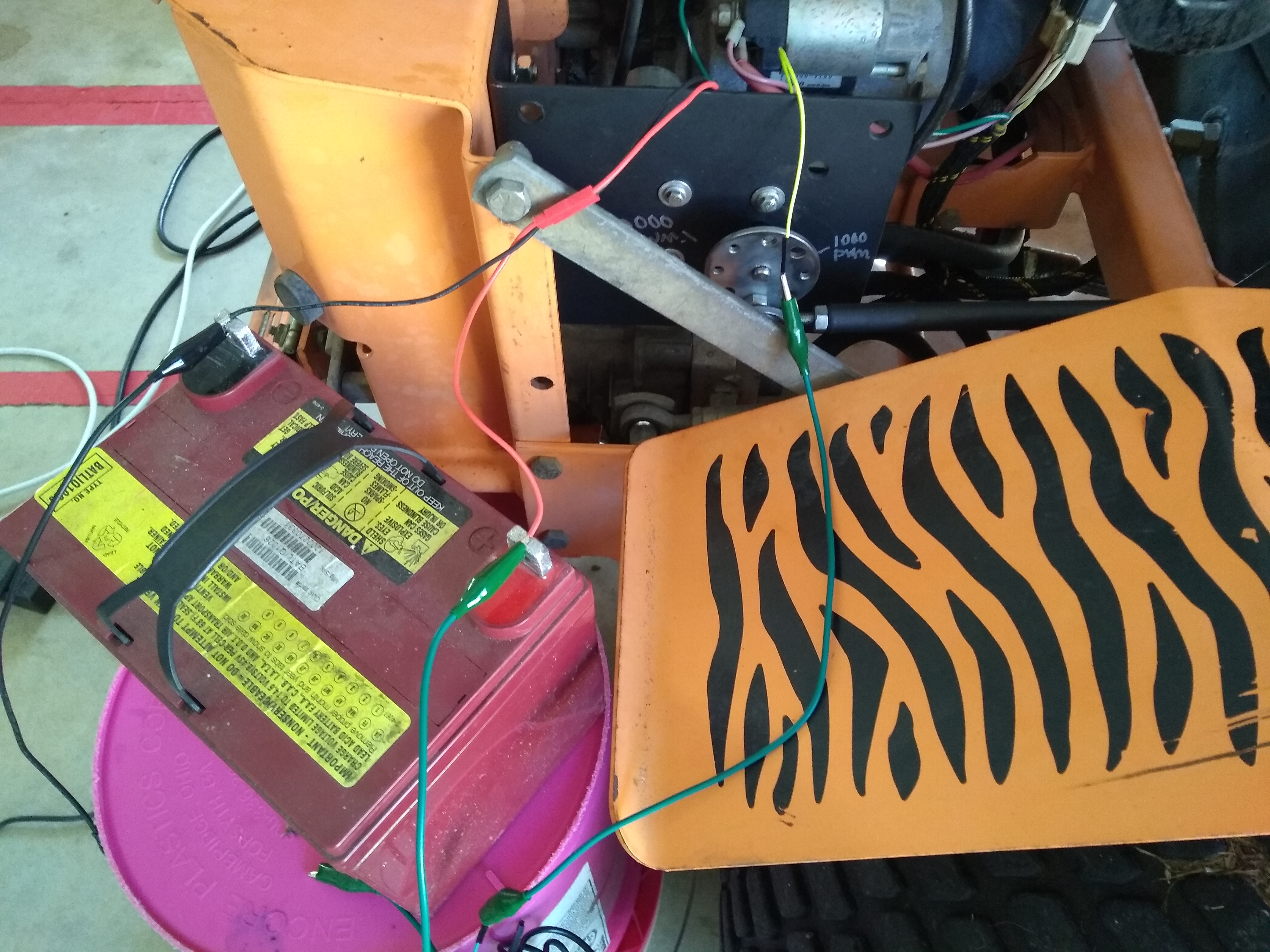
ASMC-04 Improves Upon the Old ASMC-03
It appears that the ASMC-04A is very similar to it’s predecessor, but it does give you an additional useful option: it provides a pin where you can signal the servo to reverse direction. So, from the perspective of having to remember fewer things, this would be slick on the big Scag mower because you’ll notice in the pictures below that the servos are mounted such that 1000 PWM is toward the back for one servo and it’s toward the front for the other. Again, this doesn’t “technically” matter because we’ll just end up telling Ardupilot to reverse the PWM output on the effected servo (more on this later when we talk about configuring the autopilot) — but if the ASMC-04 direction pin works as advertised (remember I haven’t yet tested an ASMC-04 servo but considering Wingxine’s outstanding reputation I would assume it does), then it would simplify another part of the setup (i.e. 1000 PWM could represent the servos moving the arms toward the back of the mower for both servos regardless of how the servos were mounted and then we wouldn’t have to tell Ardupilot to reverse the PWM output on one of the servos).
Why would I want an ASMC-04A when I can buy an ASMC-04B?
Well thank you for asking. The short answer is SPEED.
The long answer is that you may need the 04B for your application (or another similar servo from Wingxine’s diverse selection), but the 04A is precisely what we need for this application.
Here’s the deal: the 04A moves 4.17x faster than the 04B at the cost of torque — 39% less torque. Trust me though — this servo has A LOT more torque than you may imagine if you haven’t ever worked with one of these proven Takanawa 555 gear motors.
Here are the official performance specs (at 24v) for both servos:
ASMC-04A is rated at 60 degrees of rotation in 0.12 seconds -- with torque of 110kg.cm.

ASMC-04B is rated at 60 degrees of rotation in 0.50 seconds -- with torque of 180kg.cm.
Important caveat — those numbers are when the servos are powered at 24v, but I run the servos at 12v because 12v provides PLENTY of power to quickly push the control arms. I haven’t seen official numbers for 12v, but I’d ballpark guess you get half the speed/torque[3].
So, for safety, the servo’s ability to pull back the control arms (thus stopping the big mower) in the blink of an eye is very important — an extra second could be the difference between a close call and disaster.
Connecting a Mighty Wingxine Servo to a Zero-Turn Mower
As a single guy I used to marvel at how much easier it is to buy the world’s fastest superbike than to get a date with your crush (look, if you’re born with the physical gifts of ‘ole Matt then maybe getting the date is actually easier — I wouldn’t know).
Through persistence (and with the help of your ’06 GSX-R1000), you may eventually get the date.

And, of course, if all goes well, the date may turn into several dates which leads to an entirely different kind of ceremony.

Next you’re in for a real ride because a little fellow (or little lady) will likely appear who occupies such a huge place in your heart that the bike’s value, in comparison, seems negligible.

Yes, I know, this is an engineering blog and you strapping young engineer won’t believe it unless it’s in a formula. Here you go:

You end up selling the superbike for fear that it will cause your kids to become orphans, and, in an unpredictable pivot that you never imagined, you suddenly become interested in the hitherto-numbingly-boring hobbies of your forebears, such as growing absurdly big tomato plants[4].

And so, my young engineer brother, by all means take your bike for a spin[5], and somehow find the courage to ask out the girl — and remember that your decisions are rarely idempotent.
Weren’t we talking about servos?
OK, back to business. So the point of our little digression above is clearly that the easy part is buying the ASMC-04A servo from Wingxine — but the hard part is figuring out how to control your zero-turn mower’s arm with that servo.
Fear not — while I can’t tell you how you’re supposed to ask out the girl (but I do think that old-school ask-her-out-face-to-face [and often dealing with rejection on the spot] is more manly than all this Snapchat jazz the kiddos like to play these days), I can show you how we hooked up the servos.
Servo Linkage Overview
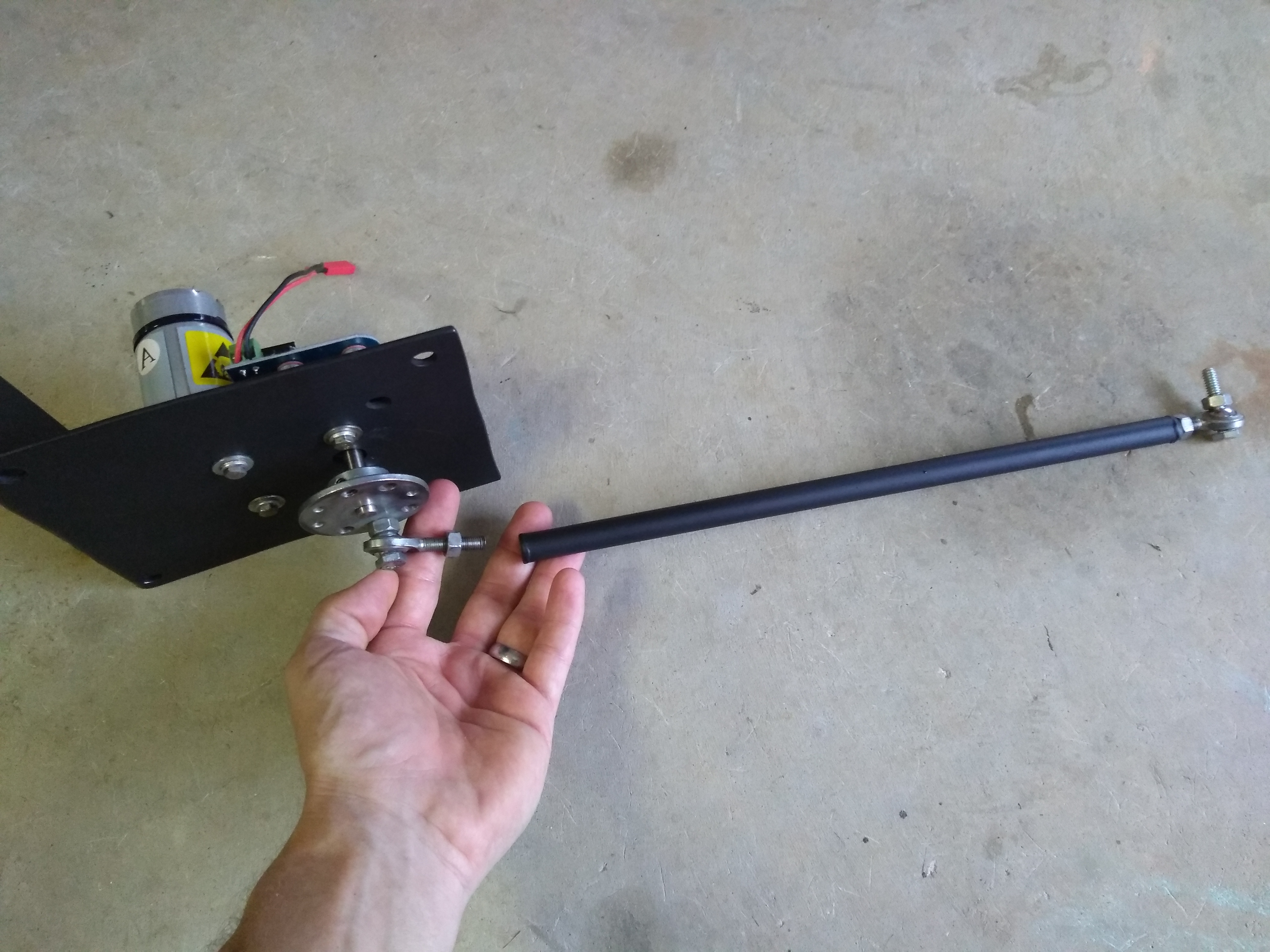
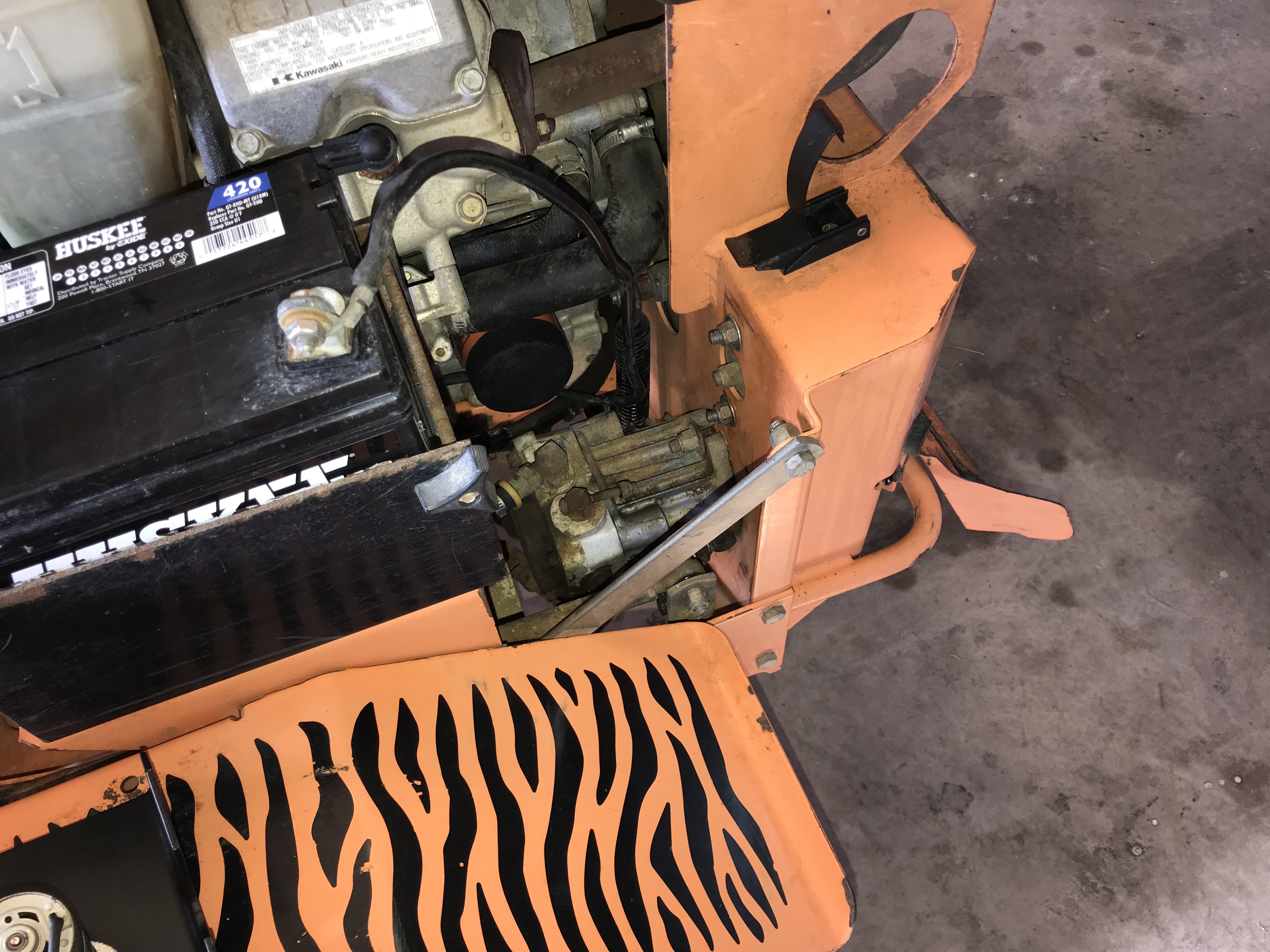
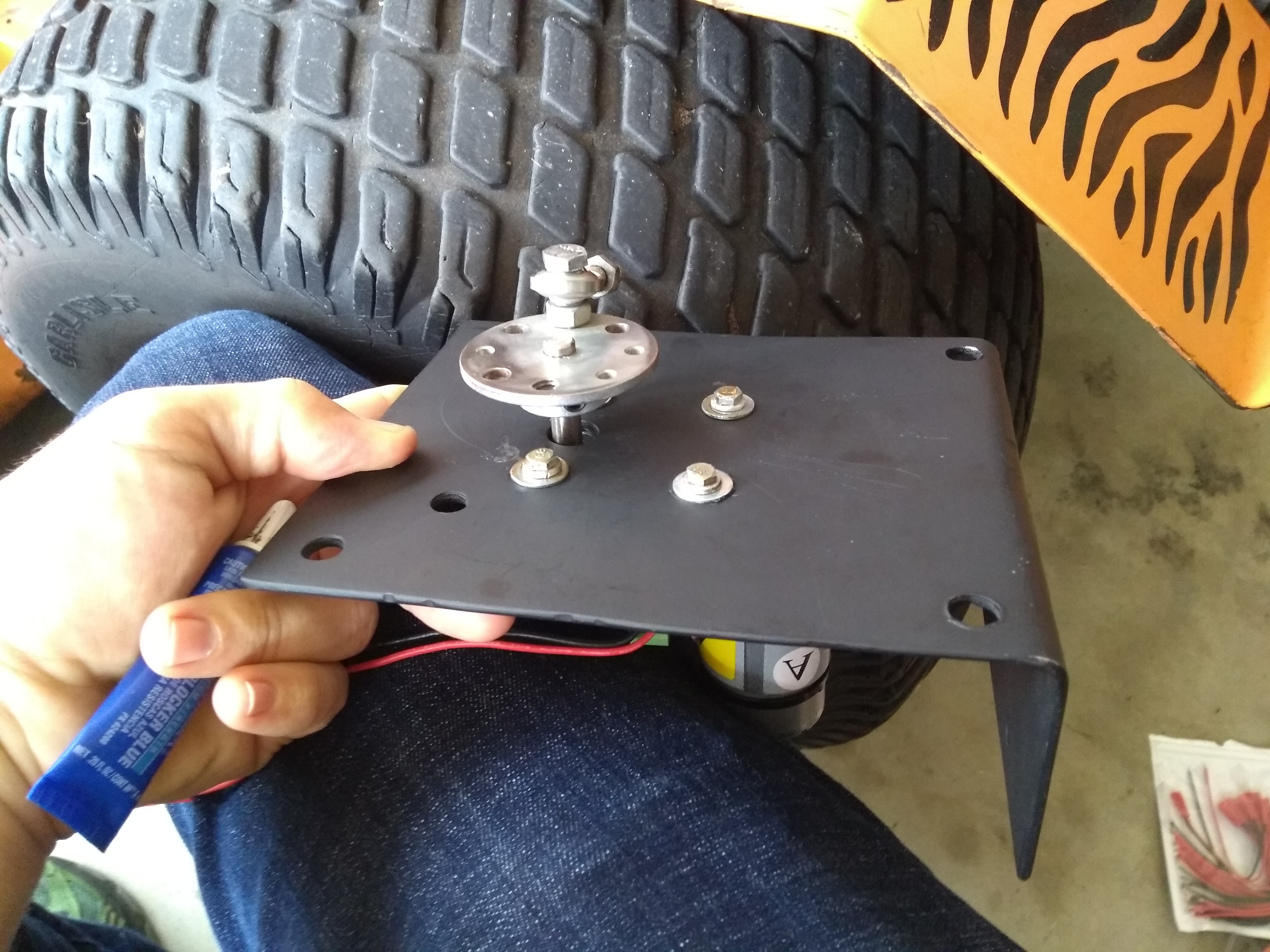
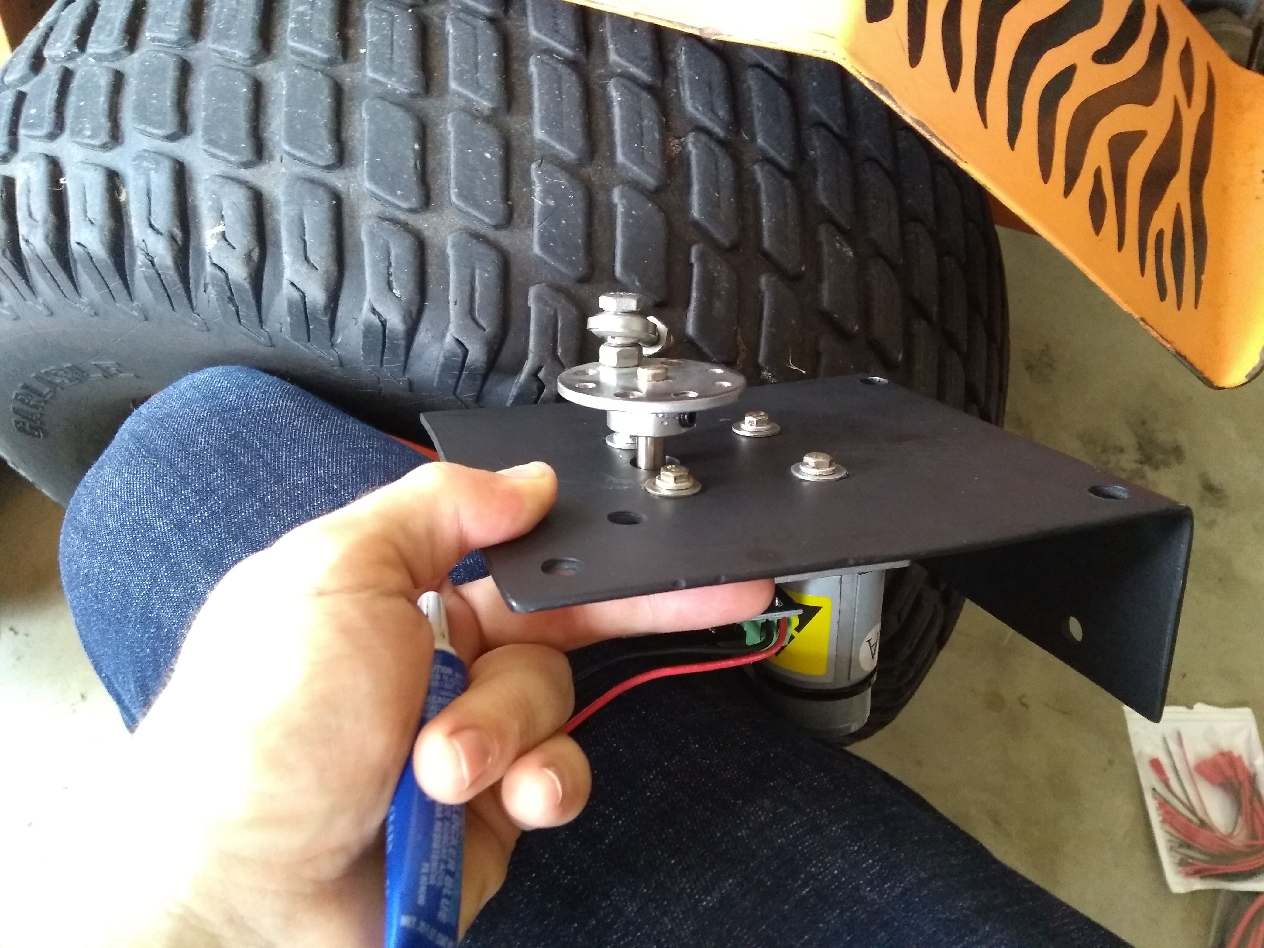
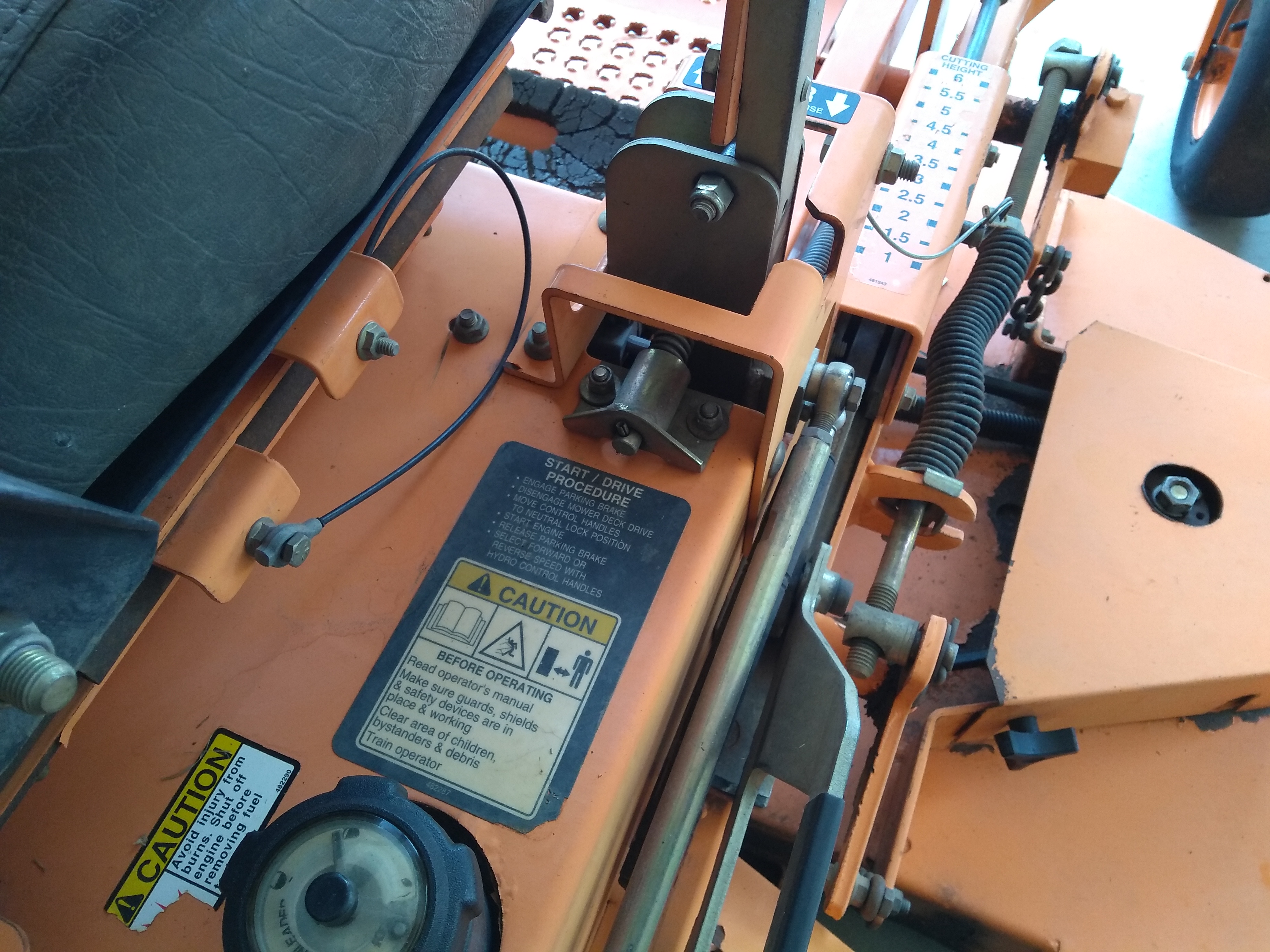
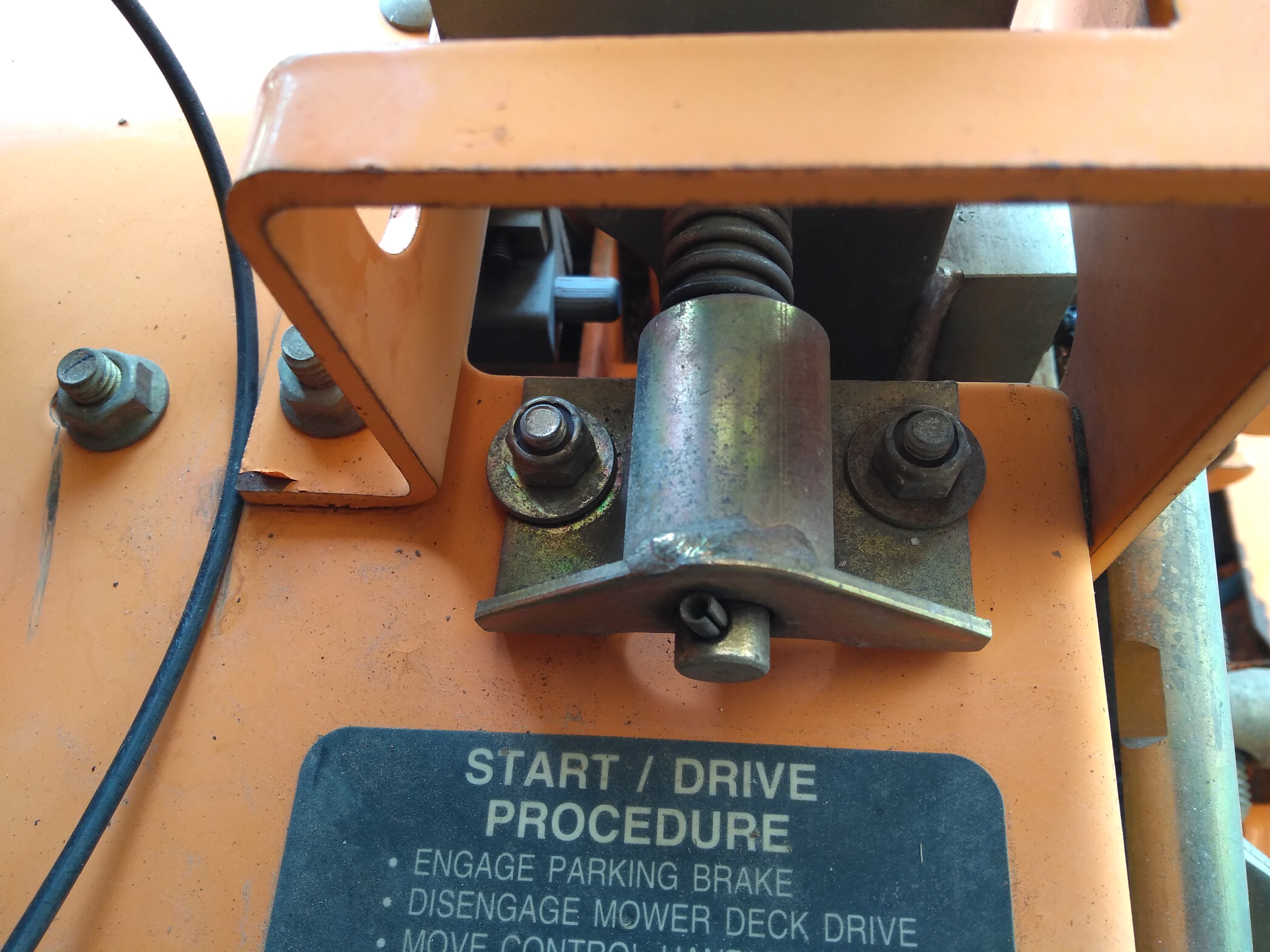
Let’s jump right to a load of photos (with scattered comments) of the servo-to-mower linkage before digging into the details:

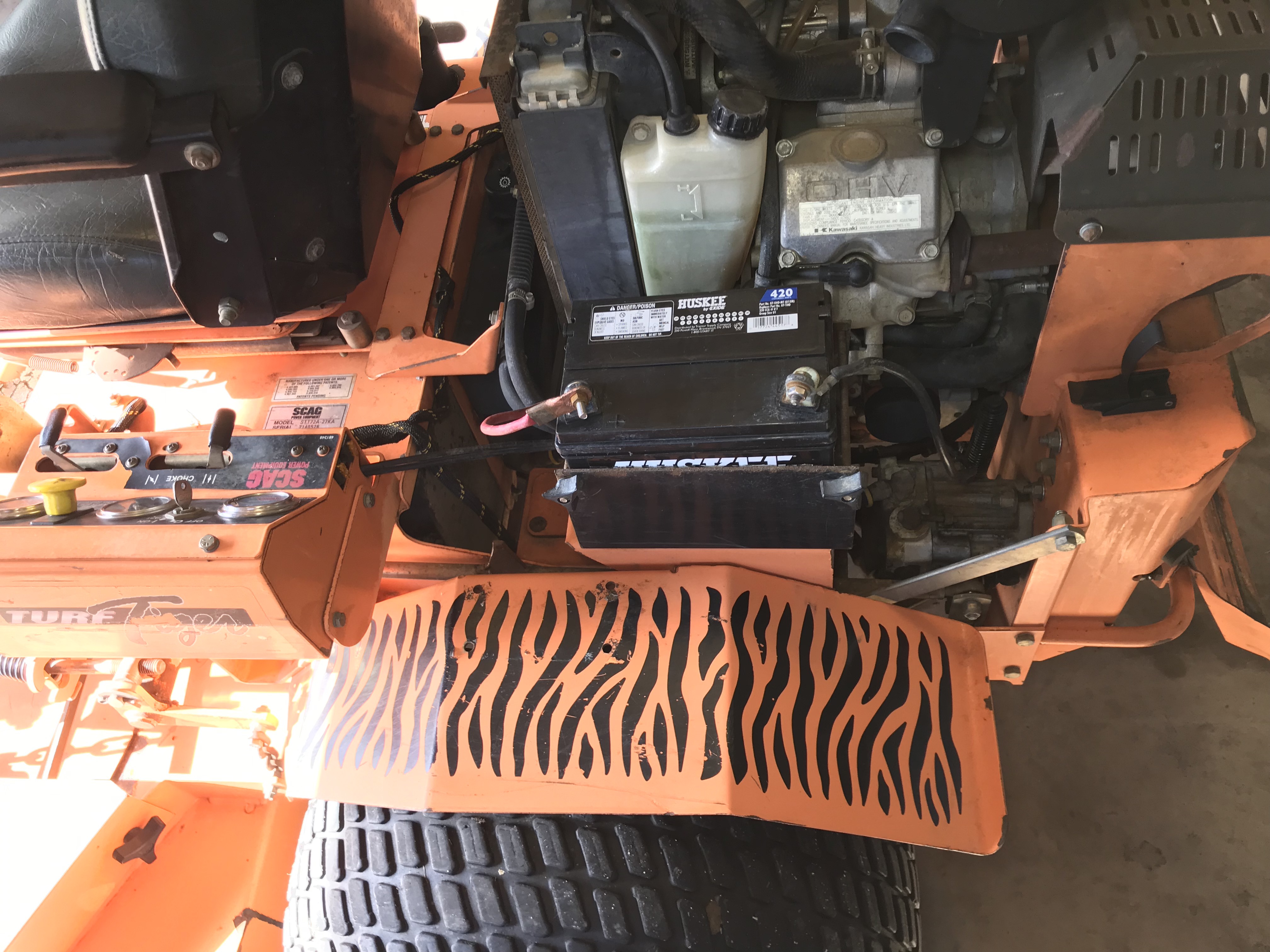


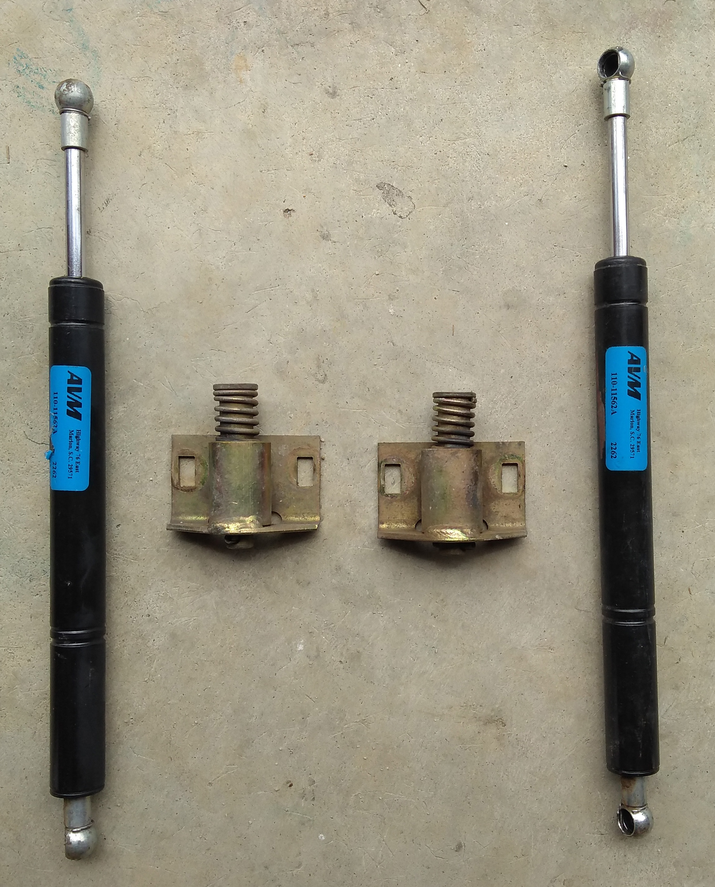
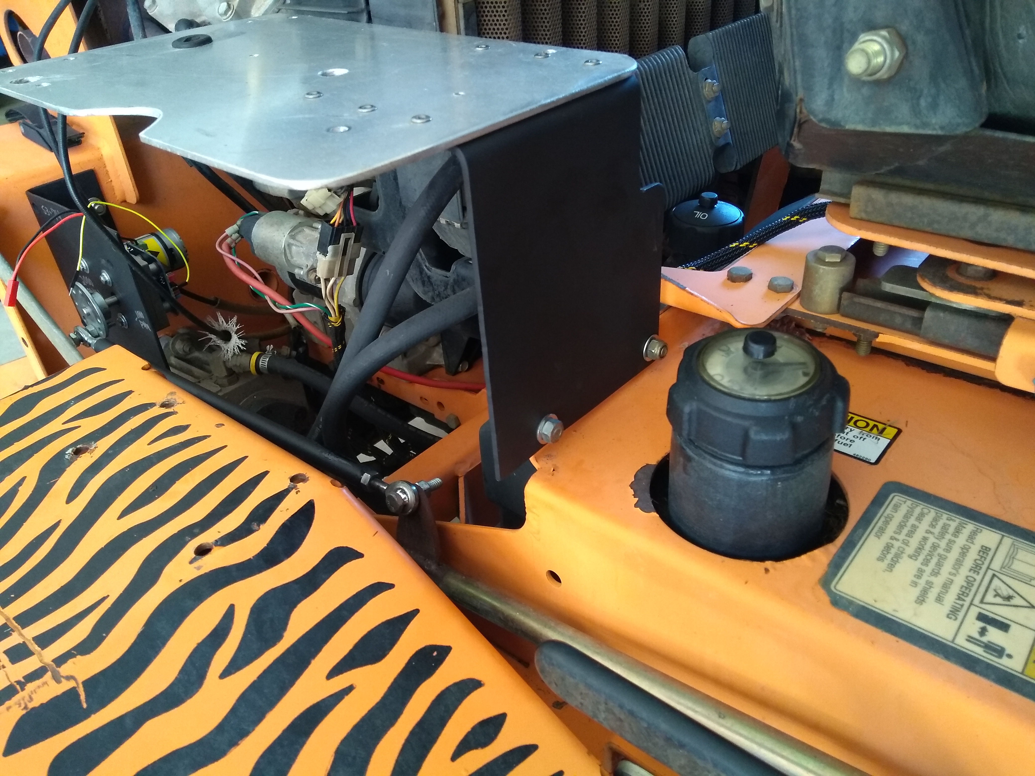
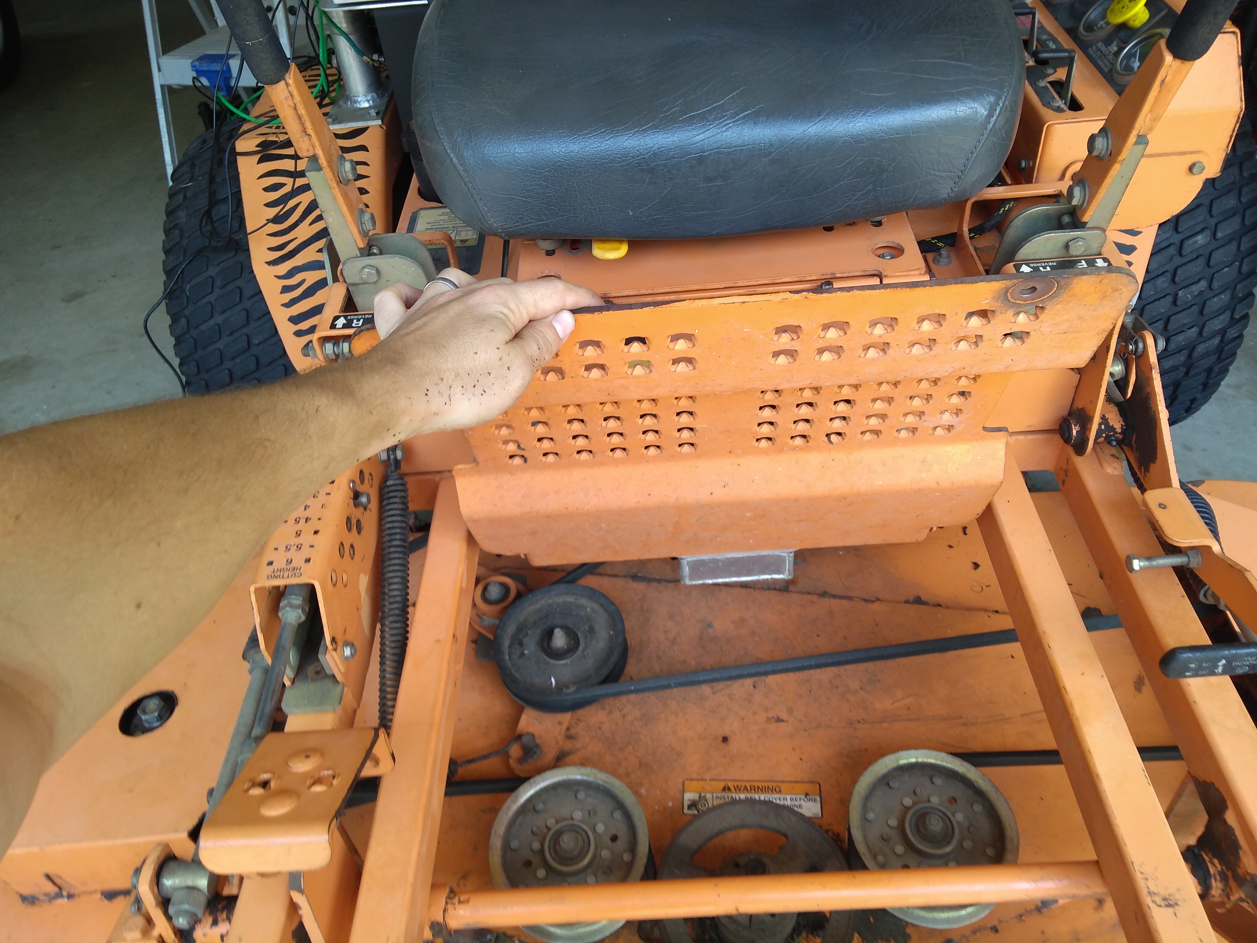
Removing the Control Arm Dampers and Reverse Springs
Our Scag has a damper on each control arm that will degrade the servo’s performance if left attached. Additionally, pulling each control arm behind neutral (i.e. reverse) depresses a metal resistance spring that adds significant torque to the effort required to move the handles throughout the reverse range of motion. When operating at 12v the Wingxine servo lacks sufficient torque to power through these springs, so we’ll remove them as well.
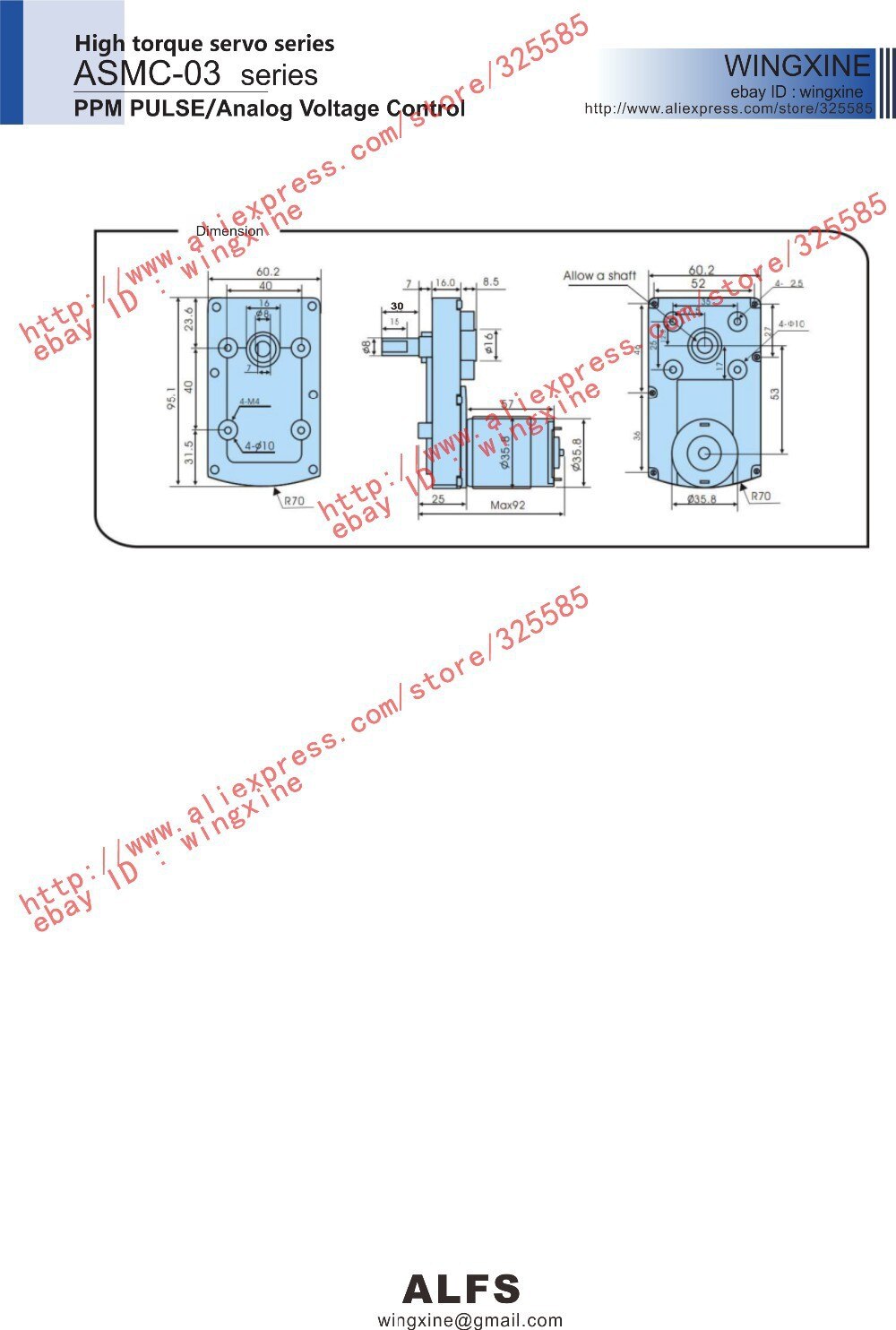
Now that the mower’s control arm dampers and the reverse-resistance-springs are removed, it’s time to build the servo linkages that will move the mower’s control arms. Let’s take a look at the parts you’ll need to make it happen (i.e. to build a set of left and right servo linkages).
Servo Linkage Parts List
- 2x Wingxine servo
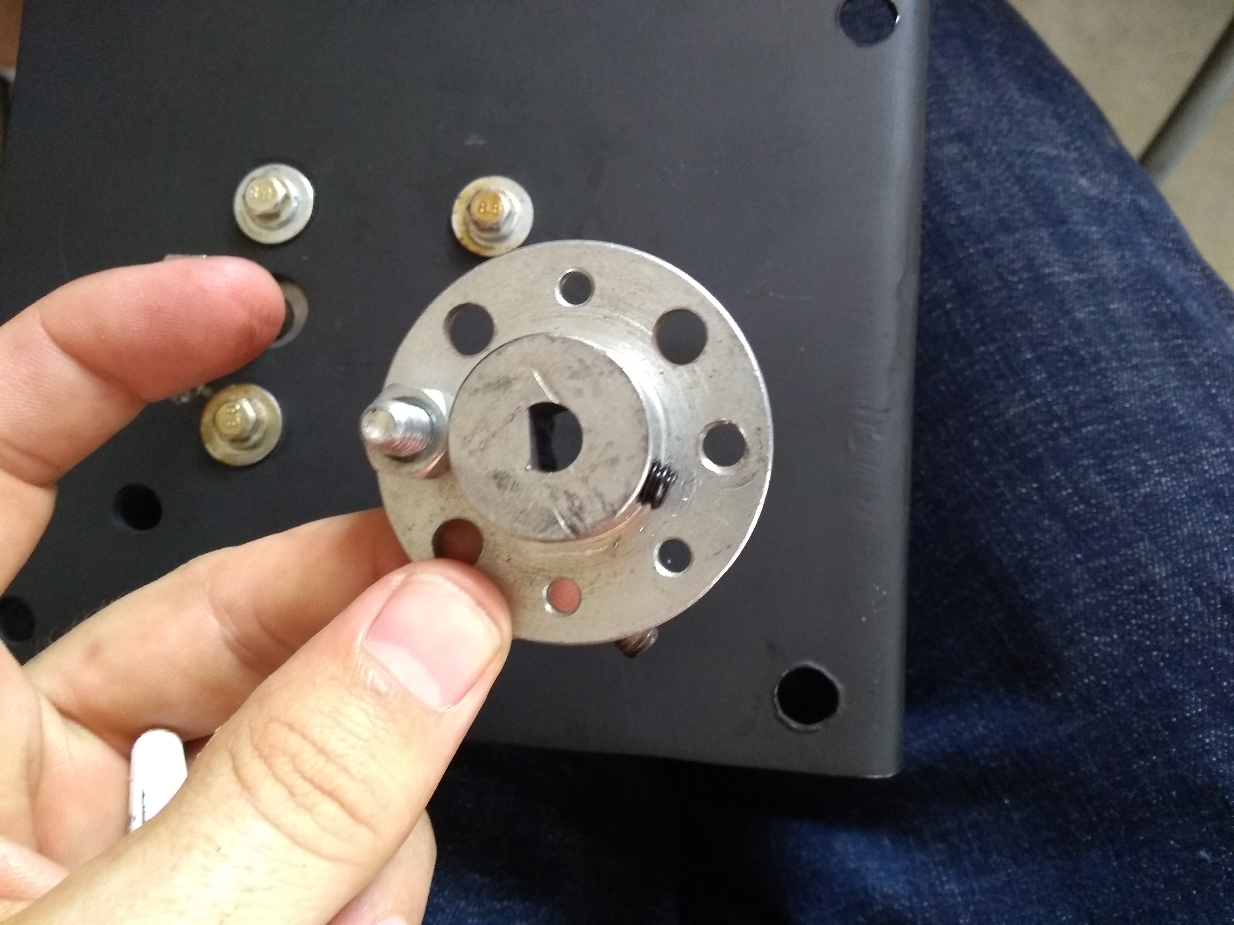
- 2x Wingxine servo plate (at the time of this writing it’s 10 bucks on AliExpress but 20USD on eBay)
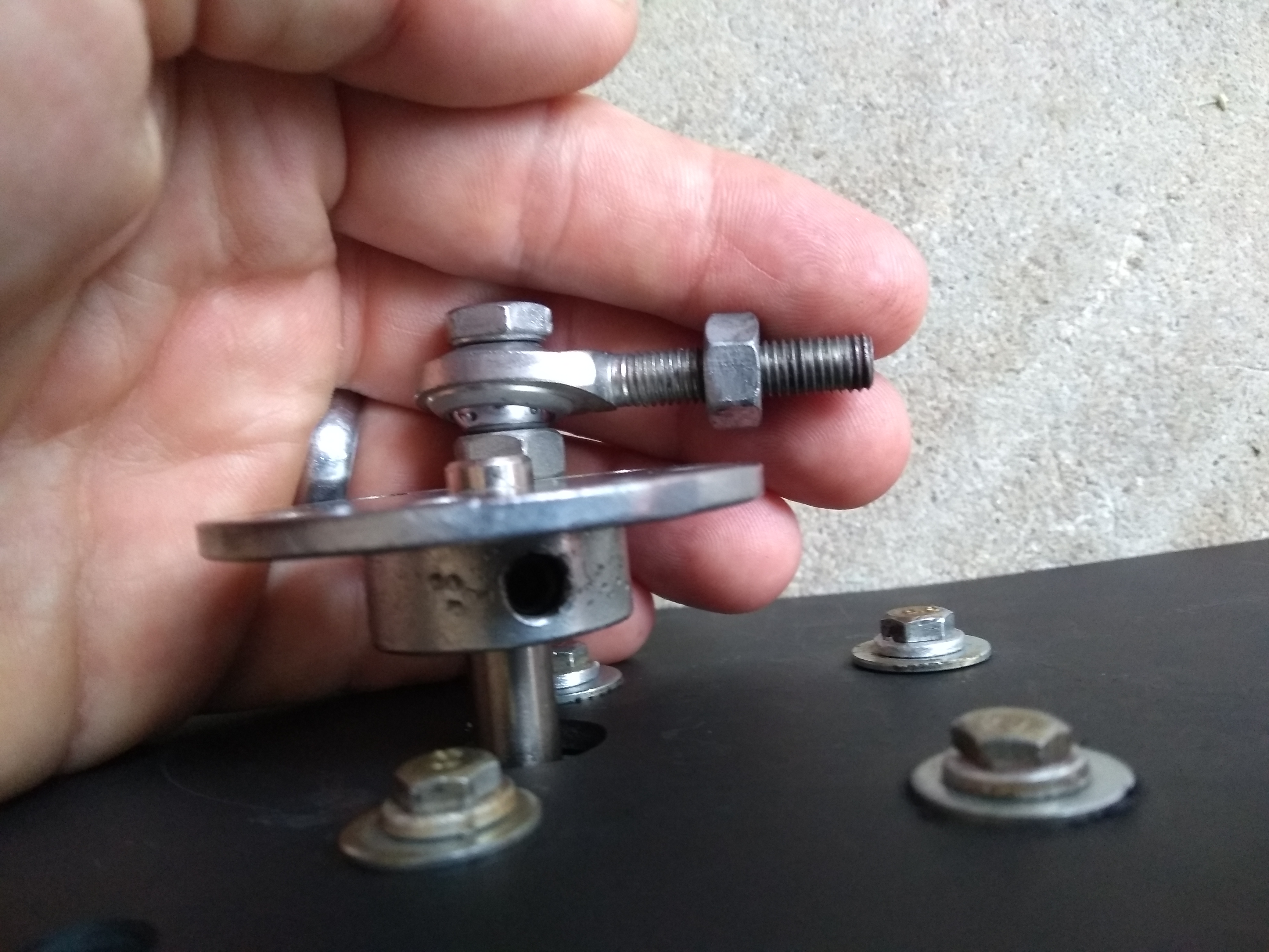
- 4x male ¼” rod end (fee free to substitute Metric components — regrettably somehow we ended up SAE for these parts).

- 4x ¼” x 1⅜” long hex cap bolts — you thread these bolts through the rod end into the servo plate to connect the rod end to the servo plate. You’ll also thread the bolts through the other rod end to connect that rod end to the metal “tab” you’ll cut out and weld to the mower’s drive arm linkage.

- 6x ¼-20 hex nuts — on each servo assembly you’ll use 2 nuts to secure the servo plate to the rod end and 1 nut at the other end of our custom 12″ servo-to-drive-arm-linkage to connect that rod end to the ⅜” steel tab we’ll weld to the mower’s drive arm linkage.

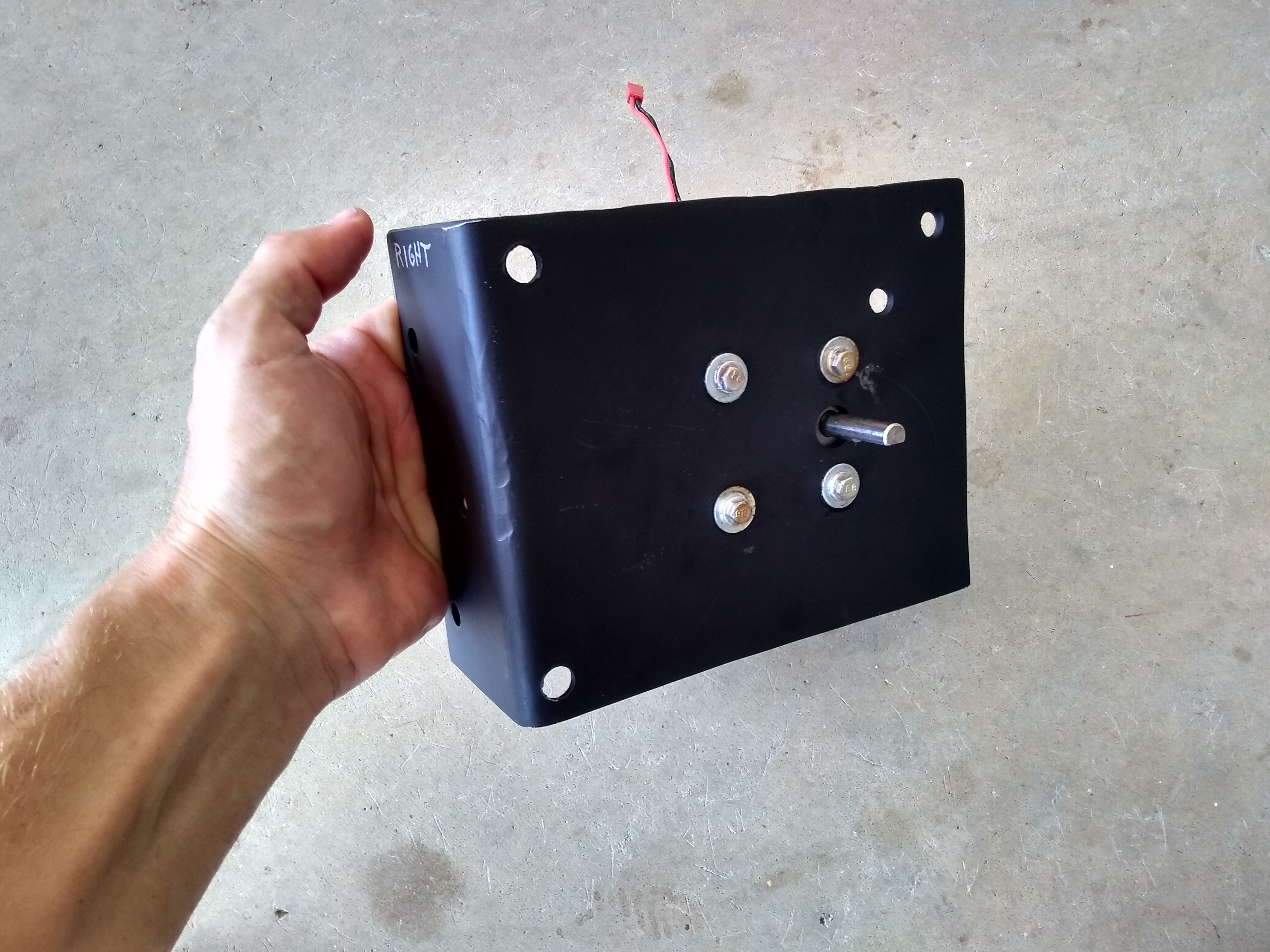
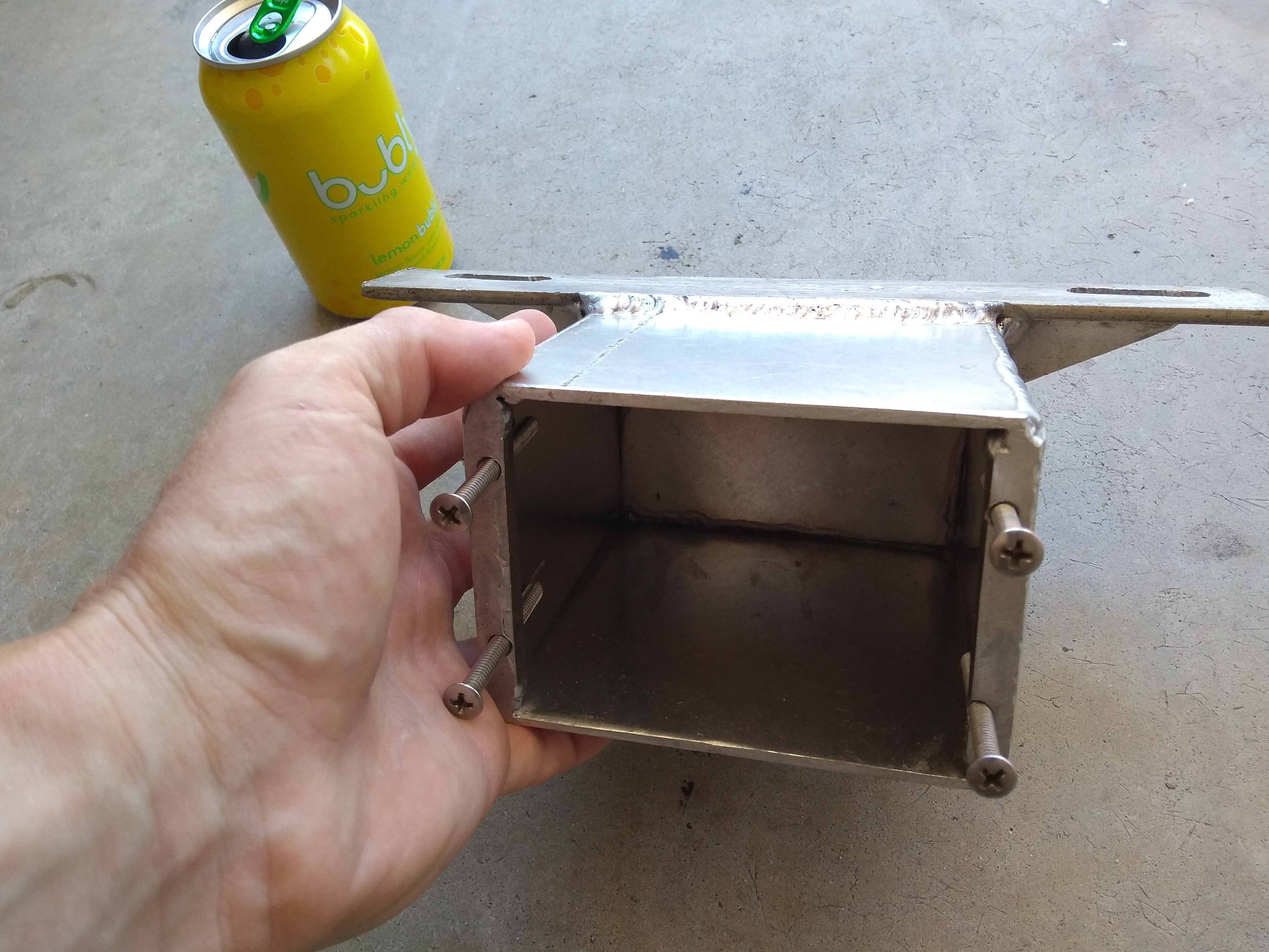
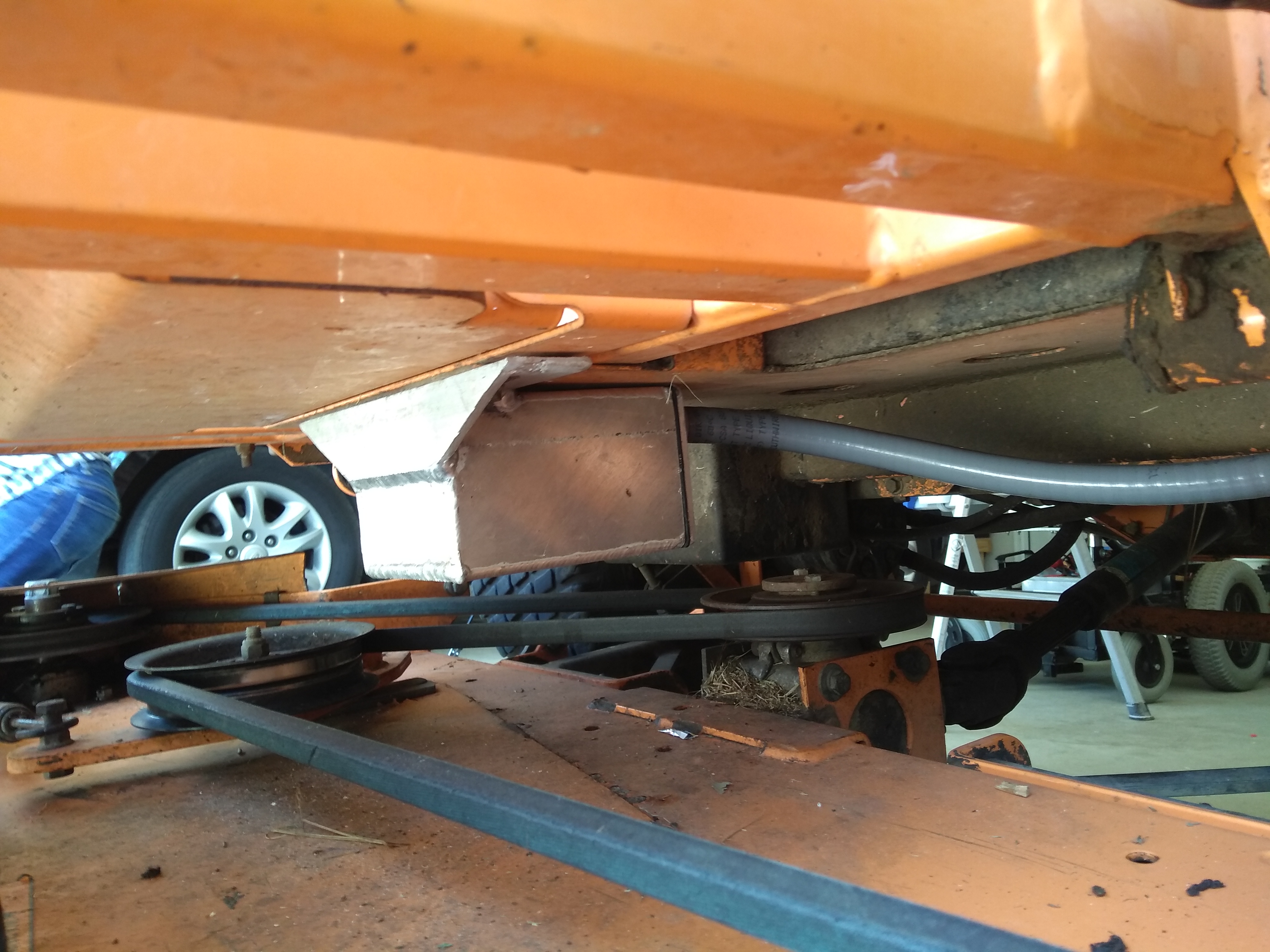
- 2x rectangular sections of 3⁄16 steel plate — you cut the plate roughly 6″ wide x 9″ long for the left/right brackets that we mount to the mower as the base for the servo. You’ll note in the pictures that we put a 90° bend (achieved with a press brake) in the plate at the 2.5 inch mark. Keen eyes may observe that we actually used ⅛ steel plate — this was an error. Our brackets flex slightly during rapid steering introducing a little imprecision into the robot’s performance.

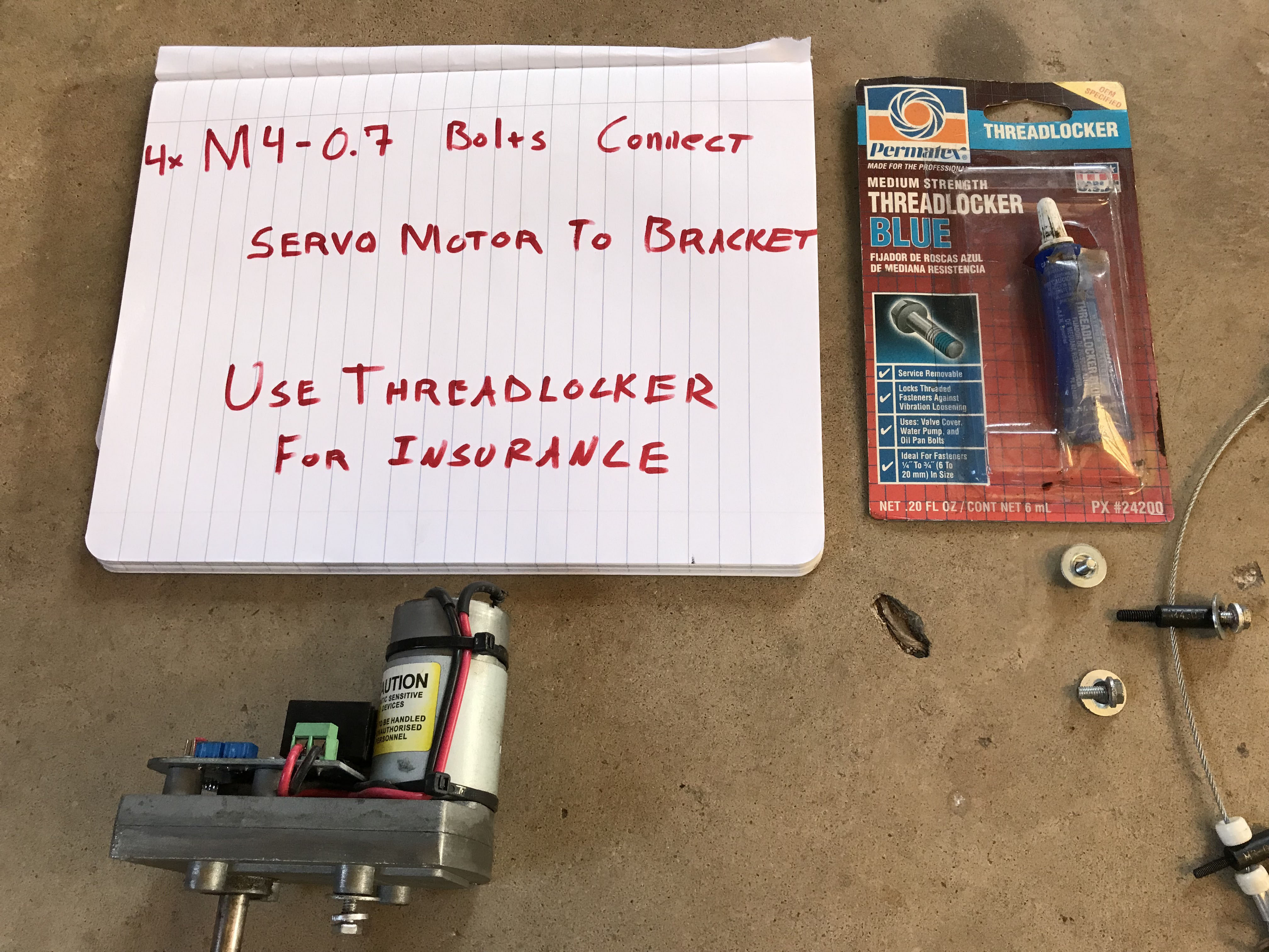
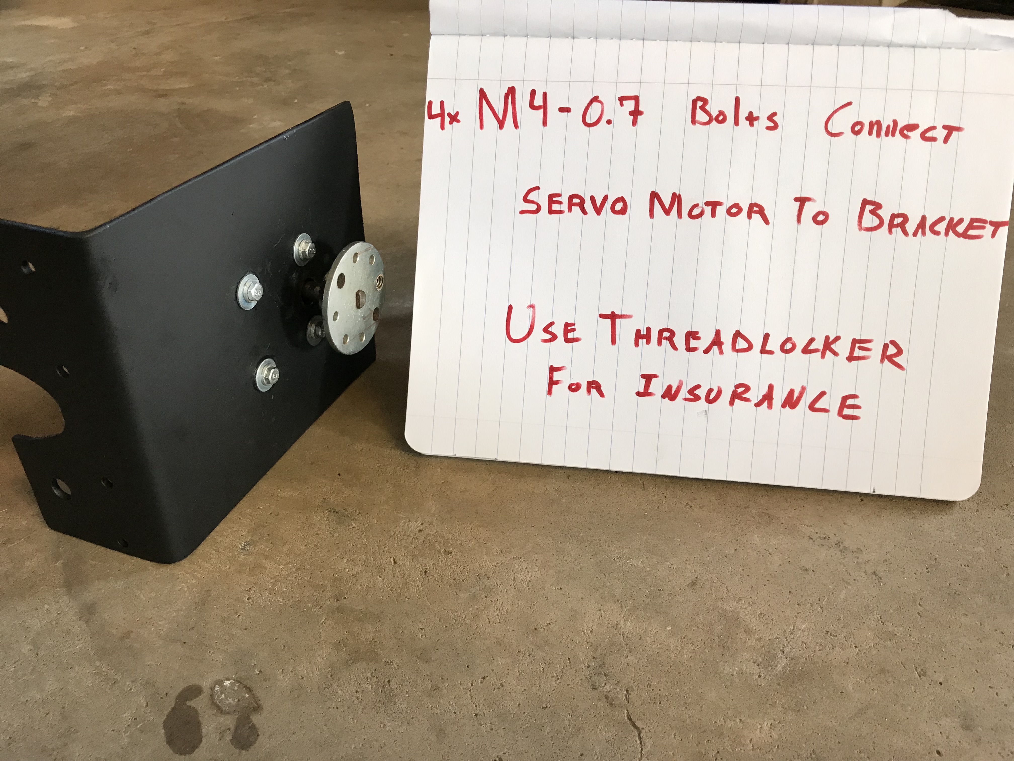
- 8x M4-0.7 12mm bolts to connect the servos (4 for each servo) to the custom brackets we fabricate.
- Washer assortment for use when bolting servo to bracket
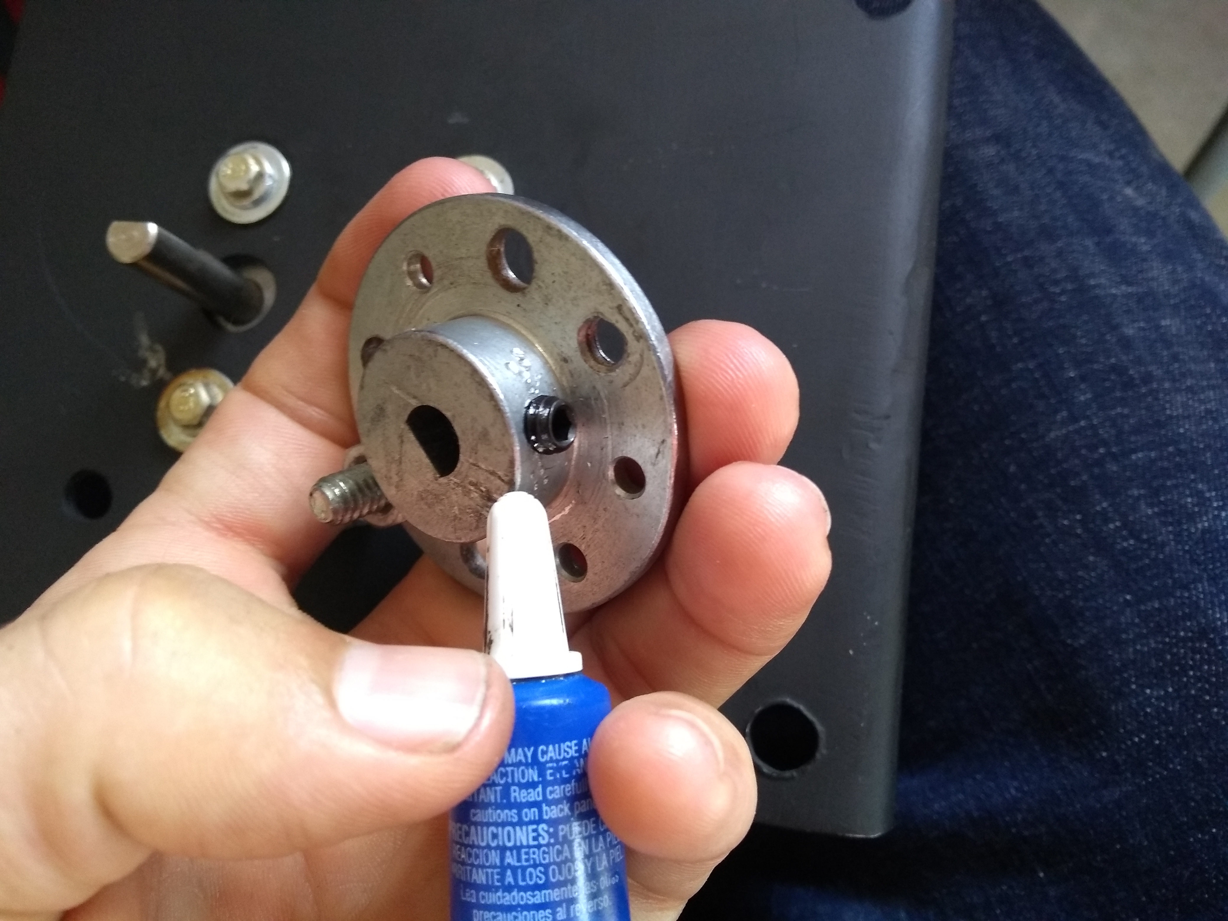
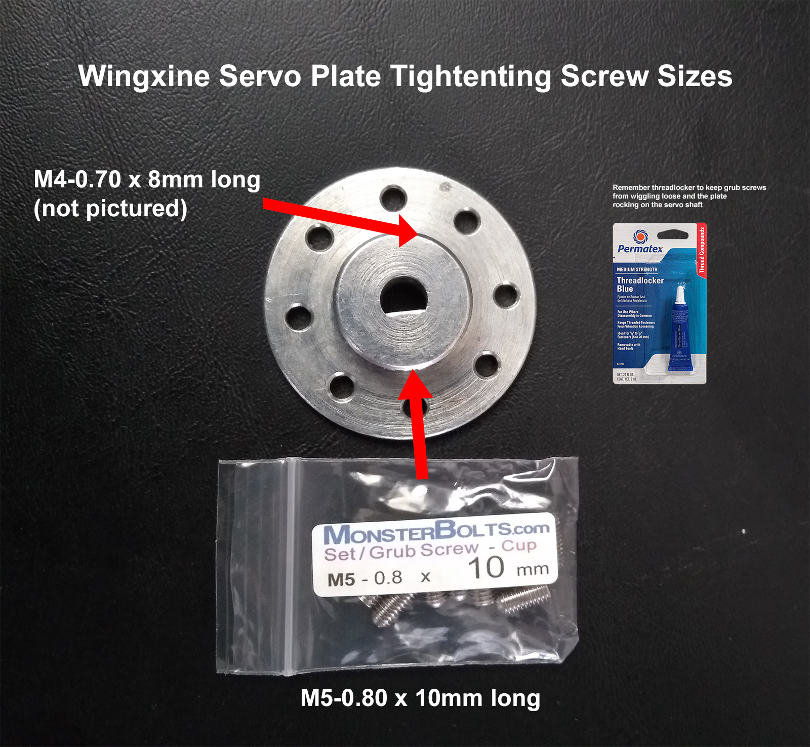
- Threadlocker to use primarily on bolts that tighten the servo plate to the servo shaft and optionally on bolts that connect servo to mounting bracket.
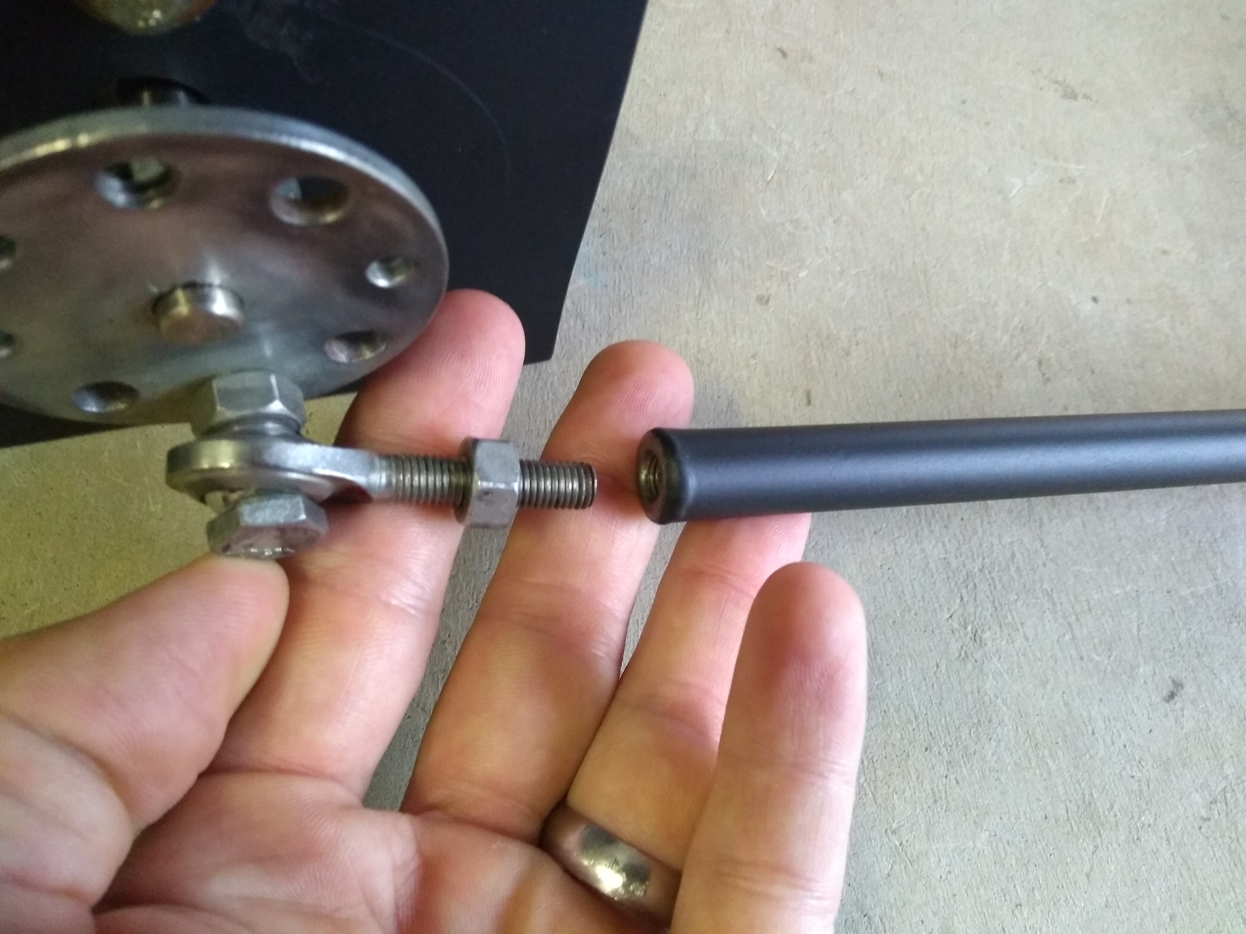
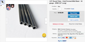
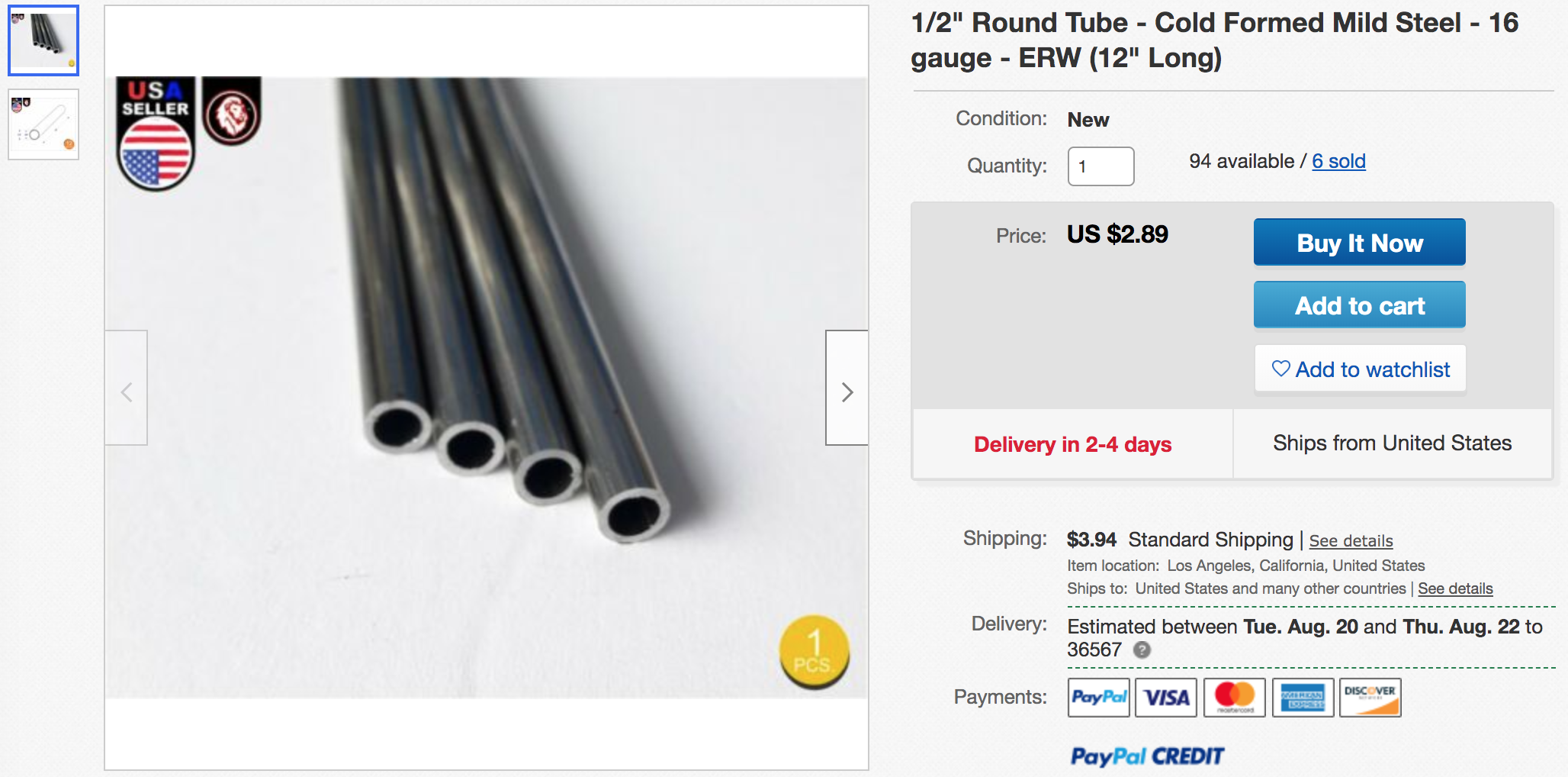
- 2x 12″ long by ½ thick steel tube. We’re going to weld a nut to either end of this tubing to create the adjustable linkage shaft between the servo and the mower’s drive-arm linkage (I realize that that sentence likely makes sense to no-one except the author, but I hope that after looking at the pictures you can see what we’re using that steel tube for — note in the pictures that the steel tube linkage is painted black).
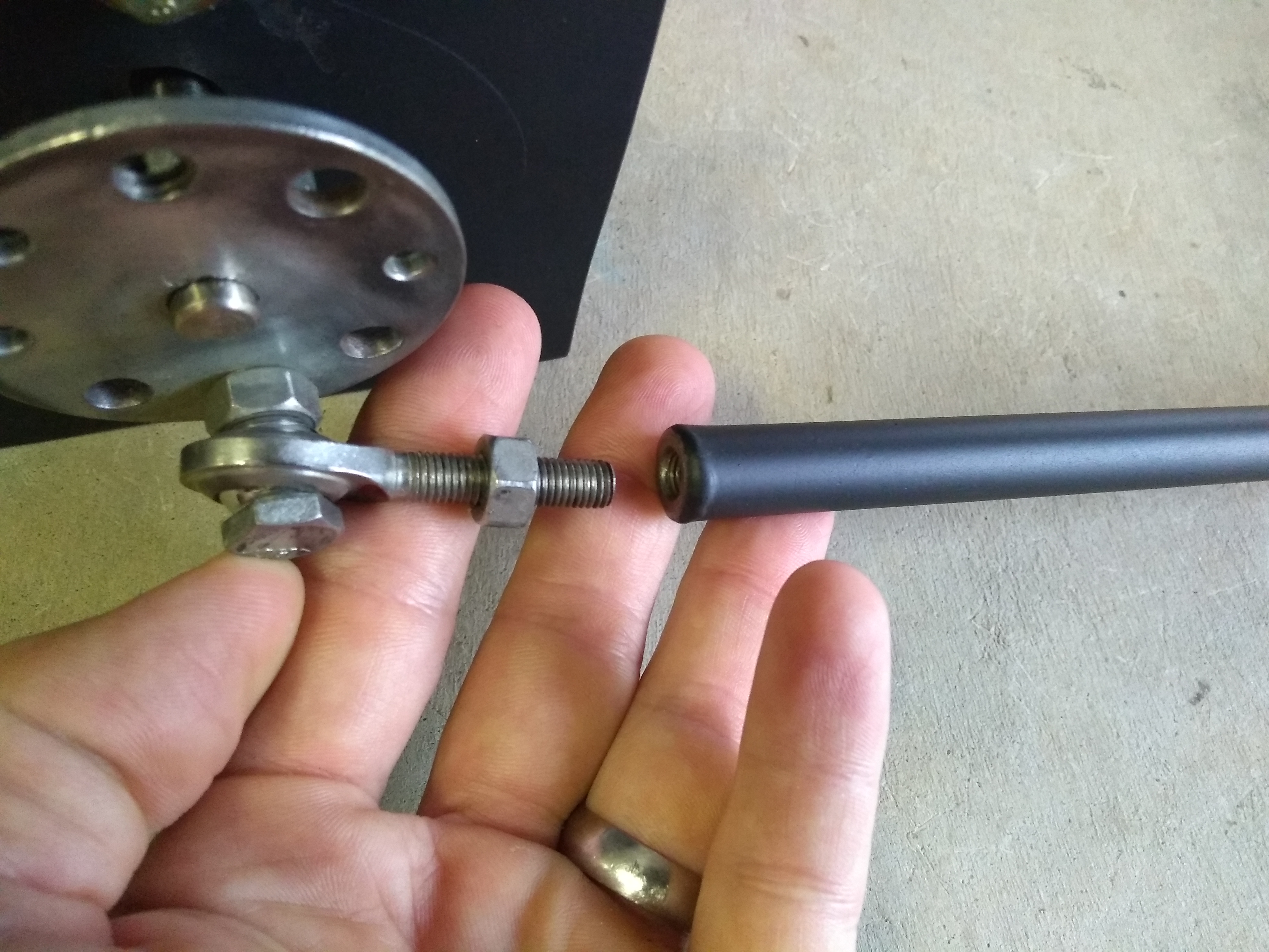
- 8x 1/4-28 nuts. We’re going to weld one of these nuts to either end of the 12″ steel tubes (note that you really can’t see these 4 nuts in the pictures — it just appears that our 12″ black tubes are threaded). We’ll then screw the male rod ends into these nuts and we’ll use this adjustability (i.e. by screwing the rod end into the nut we make the linkage shorter and by unscrewing it we make the linkage longer — this is where selecting fine threading on the rod ends pays off because it allows us to really fine tune this adjustment) to get the servos and the mower drive arms synced up very nicely. The other 4 nuts are used to tighten the male rod ends to our 12″ linkage once we’ve got the servo-to-drive-arm adjustment nailed down.

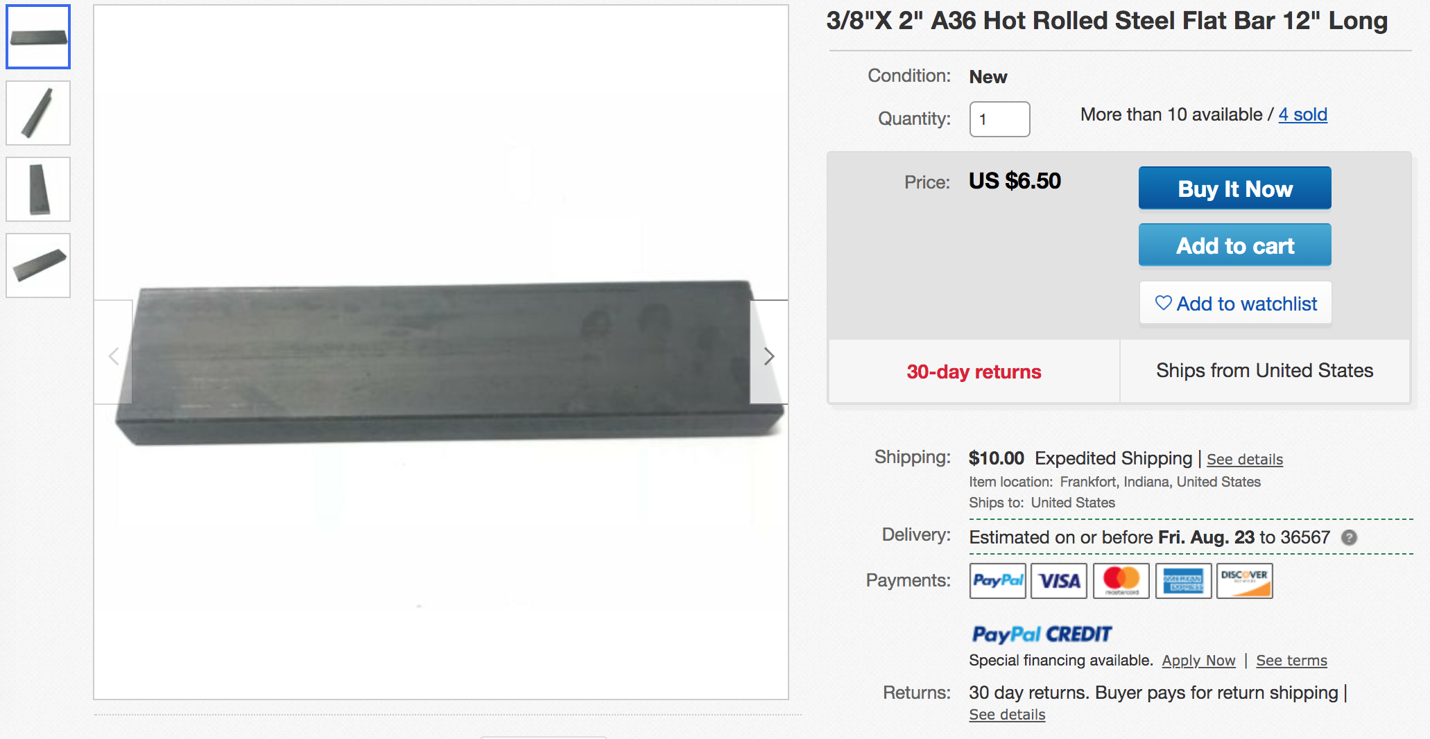
- ⅜ thick x 2″ wide steel bar like this to cut out 2 teardrop or rectangular “tabs” that we’ll weld to the mower’s drive-arm linkages.

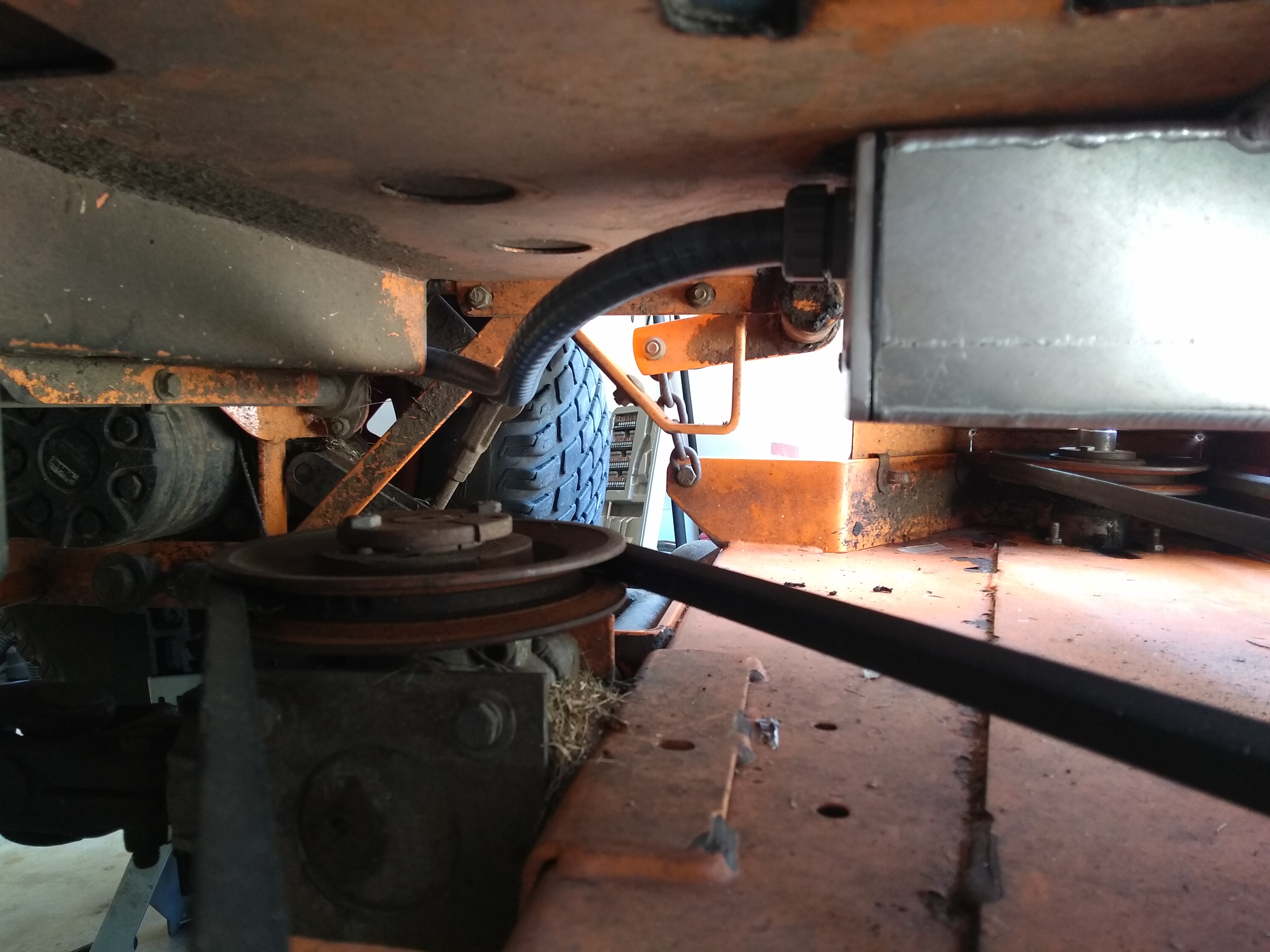
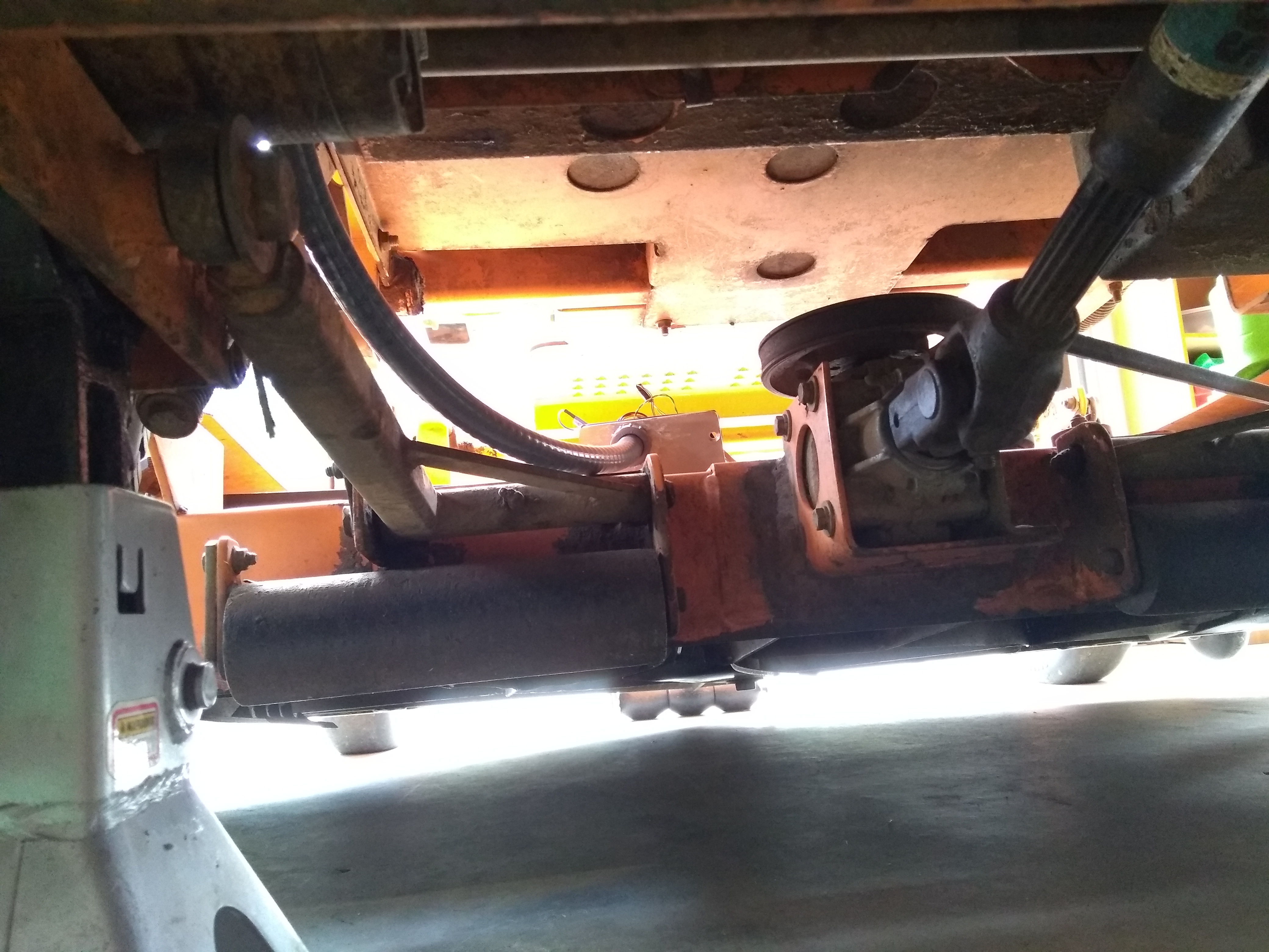
- 3 heavy duty bolts (such as these M10 – 1.50 x 20mm) and nuts (such as these) to secure the right servo bracket to the mower. Note that on our mower the left bracket happens to be lined up exactly opposite from 2 substantial bolts that connect a drive-belt pulley to the mower, so we just piggy-back off those 2 bolts to connect the left bracket to the mower.


- 1x M4-0.70 x 8mm long (or shorter) hex screw to secure the servo plate against the servo shaft.

- 1x M5-0.80 x 10mm long (or shorter) hex screw to secure the servo plate against the servo shaft.

- 1x can of Rust-Oleum flat black paint (or whatever brand/color suits your fancy).


That should be it for the linkage parts. Hopefully when you review the pictures of the linkage above you’ll get a feel for what’s going on.
Some additional observations may prove useful if you’re planning on recreating a setup similar to this.
Preparing a Wingxine Servo for it’s Ultimate Life Mission
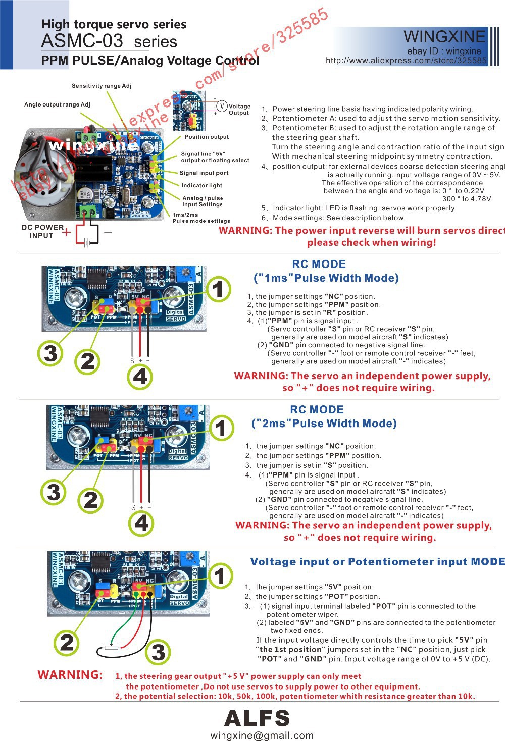
There are a few distinct steps in the wingxine_servo-to-servo_plate-to-linkage configuration dance. We have to start somewhere, so let’s start here: you’ll need to come up with some way of sending PWM values to your Wingxine servo.
Manually Controlling the Wingxine Servo From Within Mission Planner
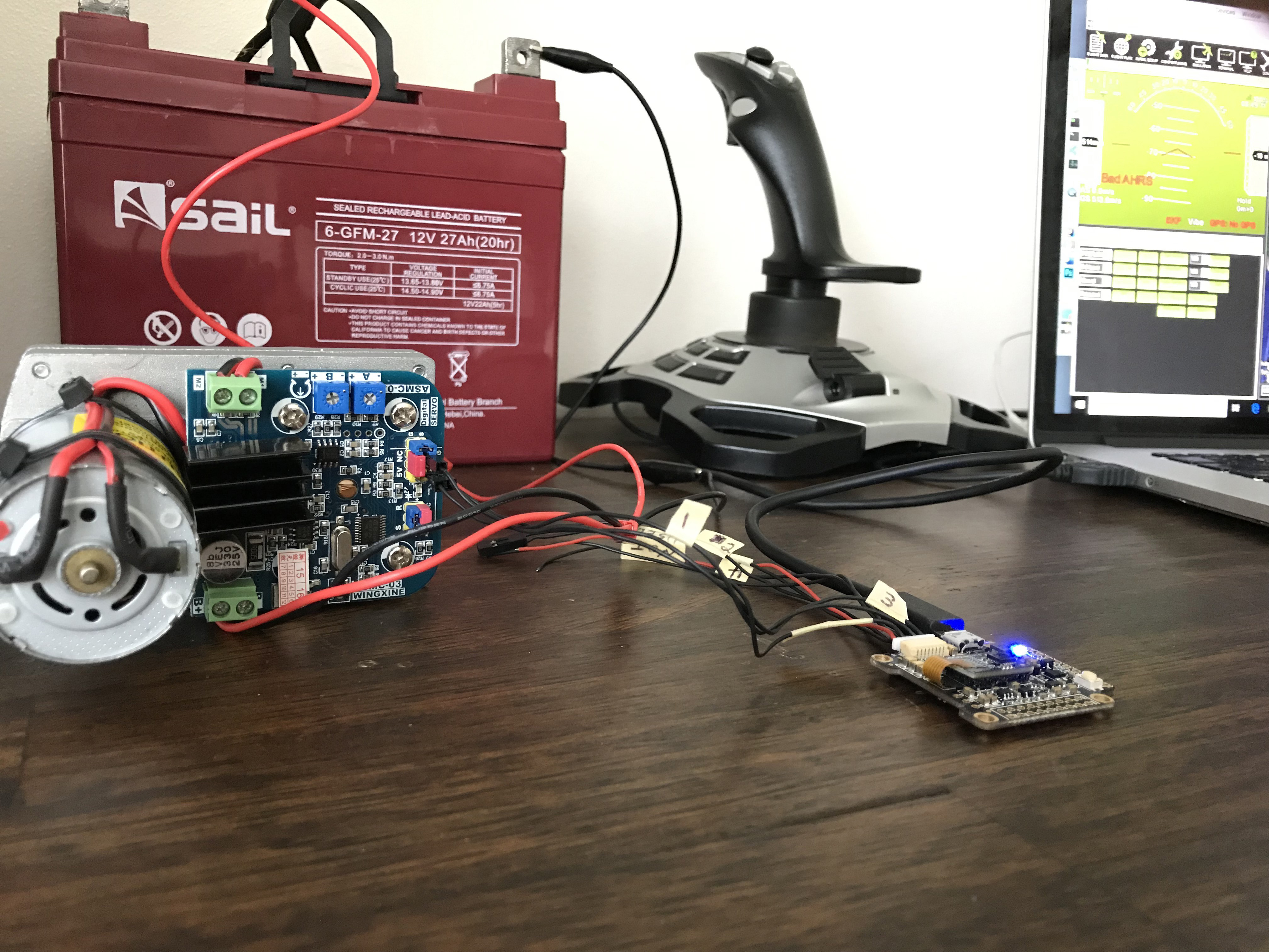
A slick (and perhaps under-appreciated) feature of Mission Planner is it’s ability to control ArduPilot via a USB joystick connected to your PC. And so, for this exercise, let’s assume you have the following components:
- A Flight Controller such as the hot-promising-and-inexpensive Kakute F7 (of course your fav flavor of Pixhawk should work as well) (also note that if you’re unboxing a fresh Kakute F7, you’ll need to follow these directions (just one time) to replace the firmware shipped on your Kakute with ArduPilot. The file you’ll load for rover is the ardurover_with_bl.hex file found here).
- A USB Joystick (don’t cheap out below this price point bro unless times are really tough).
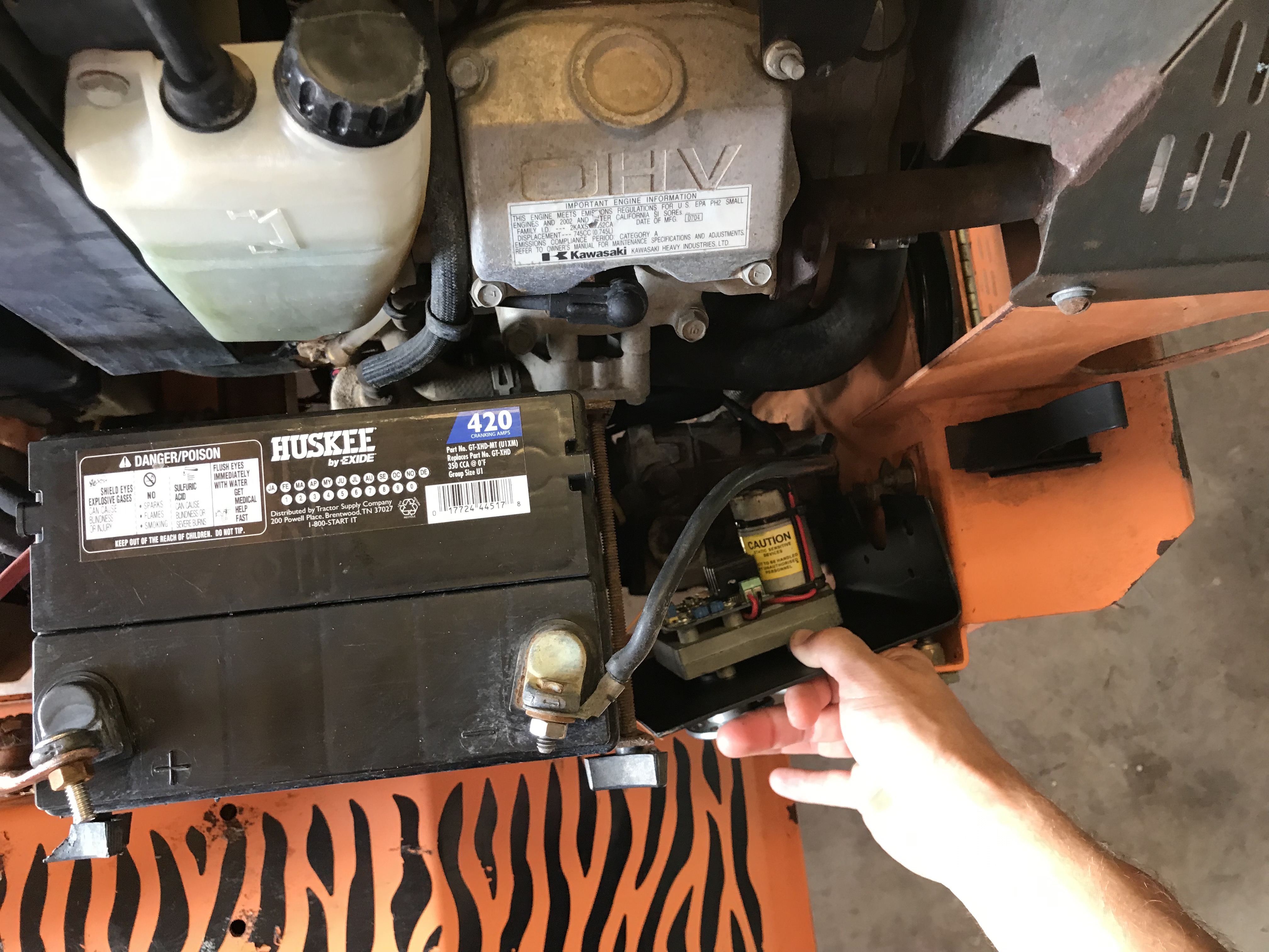
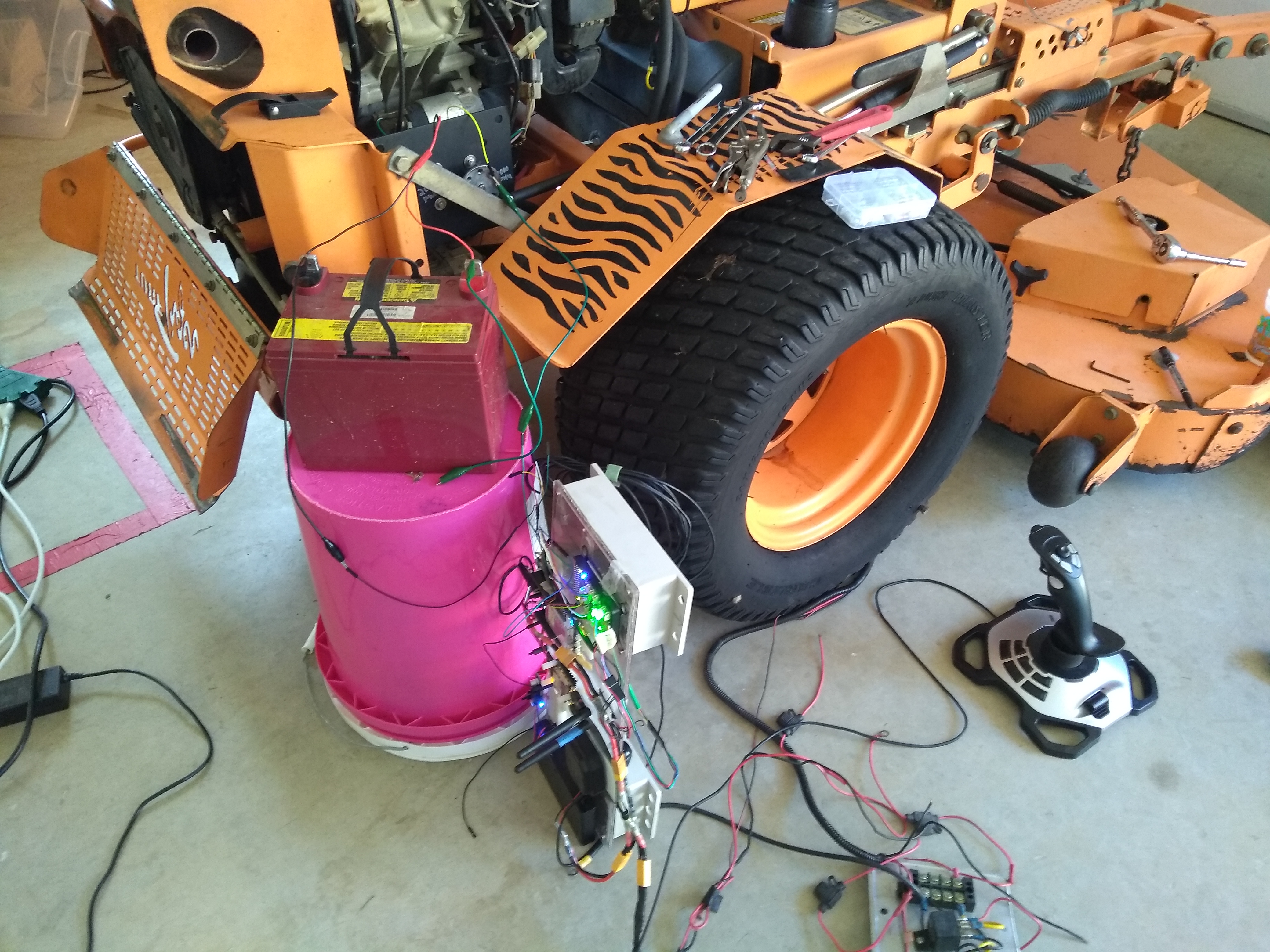
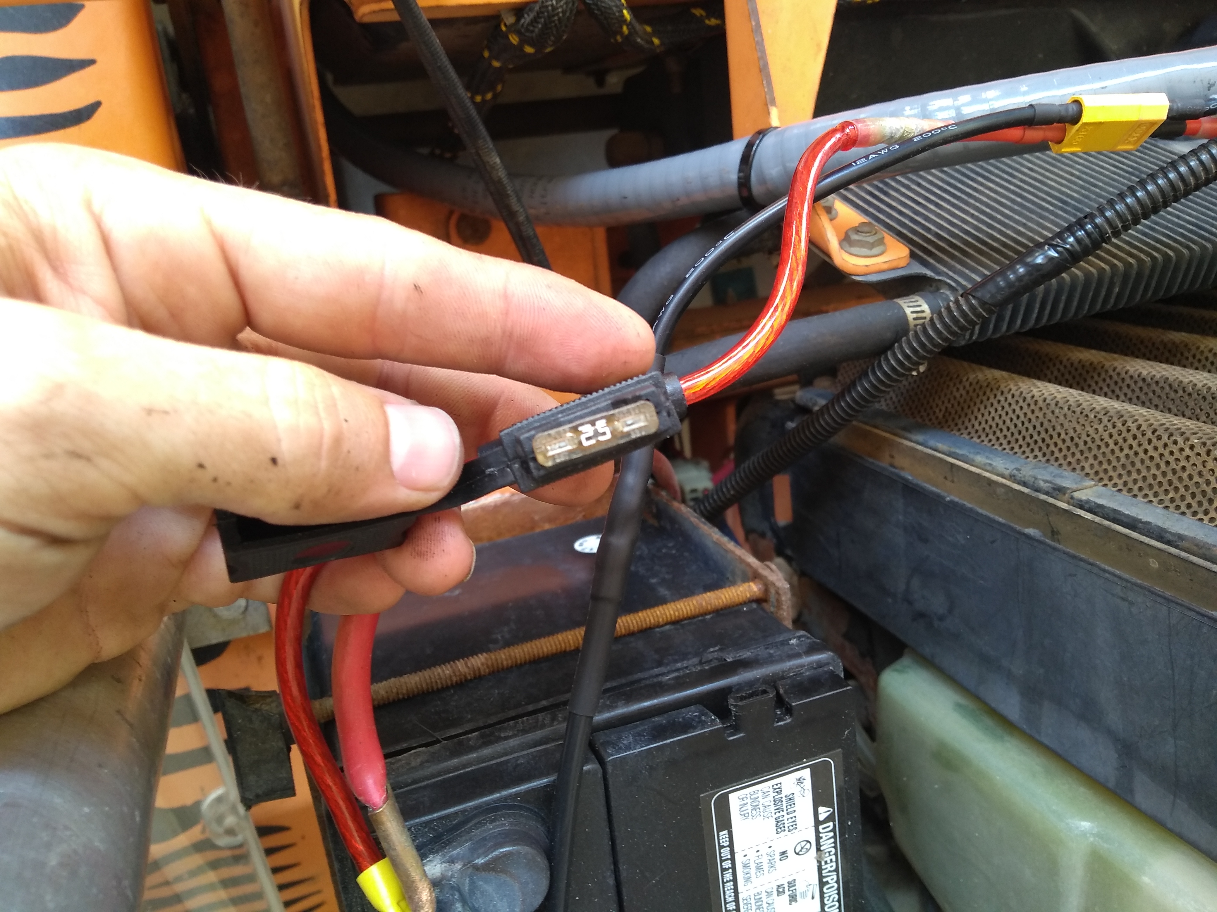
- A 12v power source (such as a barely-breathing red lead-acid battery salvaged from yet another electric wheelchair I recently brought home to the rolling-but-understanding-and-beautiful eyes of the wife) and some way to connect it to the Wingxine servos (such the aligator clips and JST connectors I use below).
- Some random wire to connect Servo Output 1 from your Flight Controller to the Signal pin of your Wingxine servo.
- Another random wire to common up the ground between the Wingxine servo and your flight controller — in other words (i.e. if you’re new to electronics world) suppose your flight controller is powered by your PC via USB, but the Wingxine servo is powered by a 12v battery. You achieve this “common up the ground” idea by connecting the Ground/GND/G pin from the Wingxine servo to a Ground pin on your Flight Controller. Guess what happens if you forget this step? Usually nothing 😉
- Of course you’ll need Mission Planner and your choice of Wingxine servo and Wingxine servo plate (links above).
You’re going to hook all of those components together so that you get something like this:
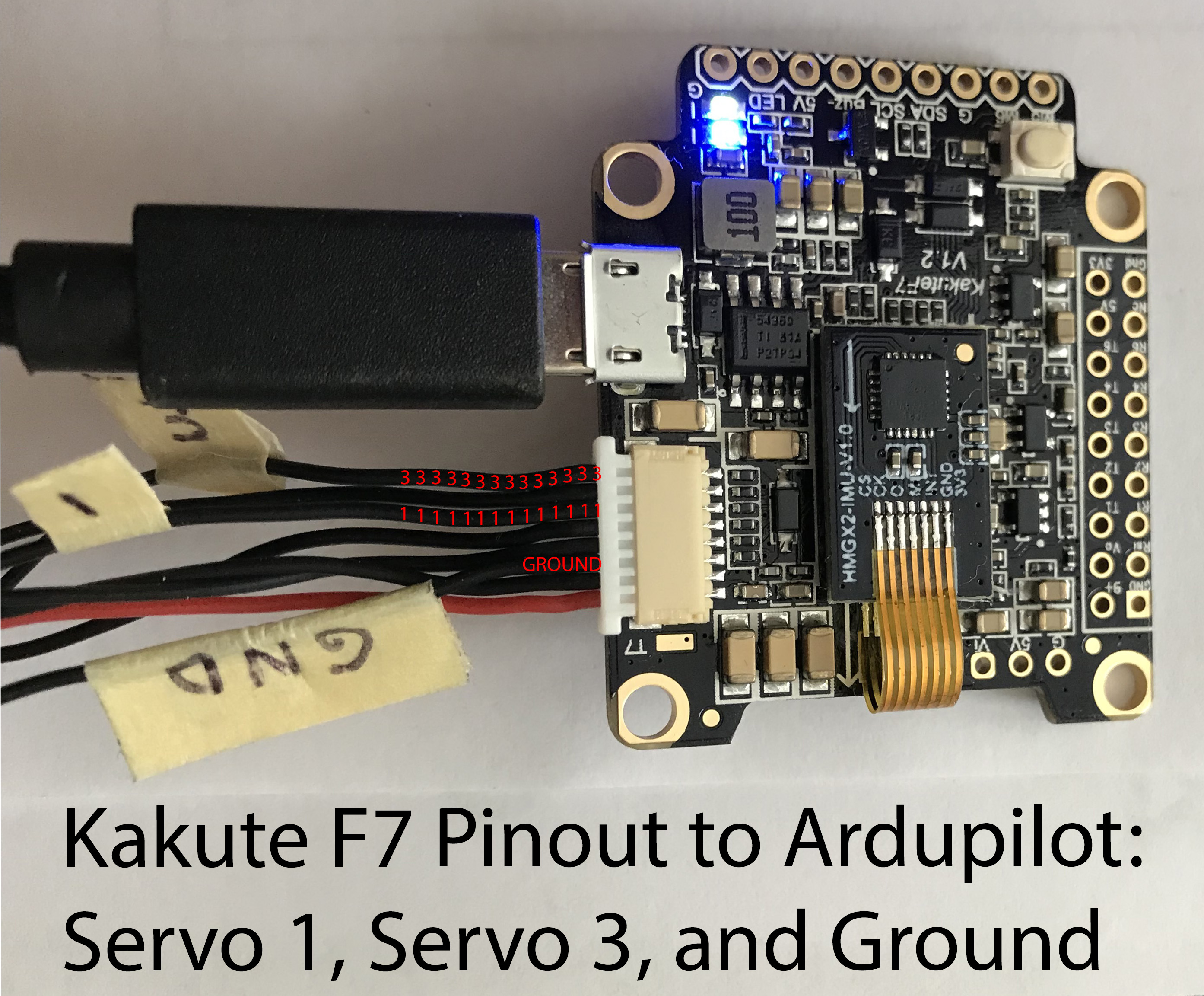
If you’re using a Kakute F7, then it may not be obvious to you (as it was not to me) which wires in the F7’s wiring plug correspond to ArduPilot Servo Output 1 and Servo Output 3 (i.e. as a fun little twist, Kakute actually calls the Servo Output 3 wire “M4” and the Servo Output 1 wire “M2”). Here’s a little picture I made to hopefully clear that up:
Assuming you’re rolling a wingxine_servo-flight_controller-joystick-mission_planner setup similar to the pictured above, let’s talk about the ArduPilot configuration we’ll set from within Mission Planner so that we can send PWM values to the Wingxine servo.
Mission Planner Joystick Configuration Steps
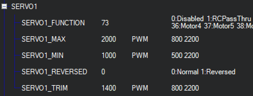
- First off, go to Config/Tuning –> Full Parameter Tree –> SERVO1 and set the values like these:
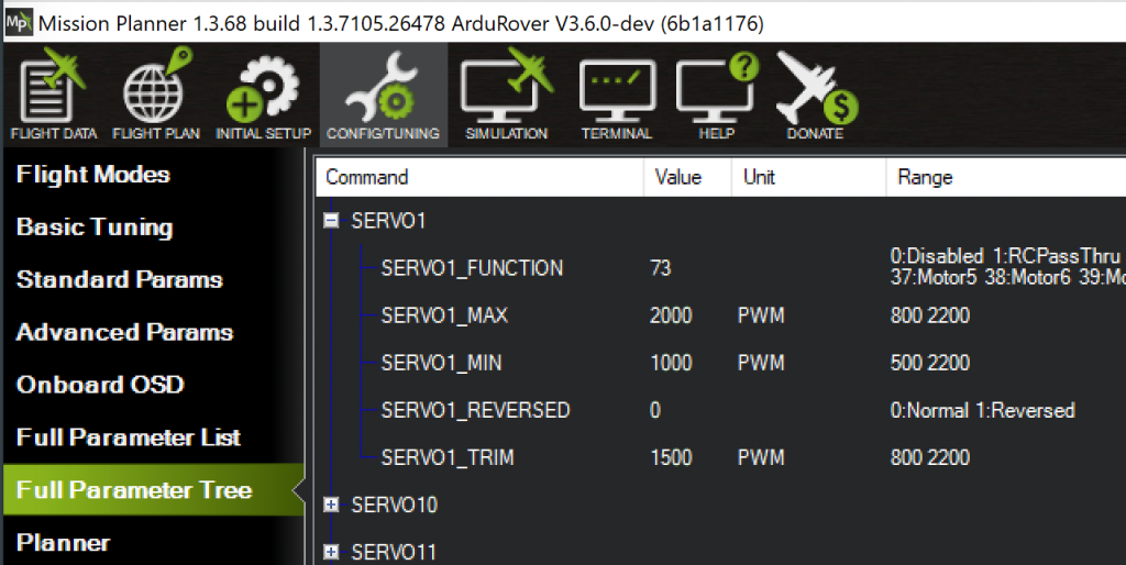
SERVO1_MAX is the PWM value that ArduPilot will send to the Wingxine servo when we push the joystick all the way forward. SERVO_1_MIN will correspond to the joystick pulled all the way back. SERVO1_TRIM is the PWM value ArduPilot sends to the servo at rest — we’ll use this value later on to dial in the exact PWM value that moves the mower’s handle to the neutral position. - Now find the PILOT_STEER_TYPE parameter and set it like so:
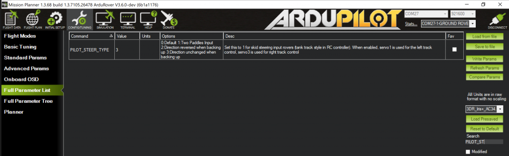
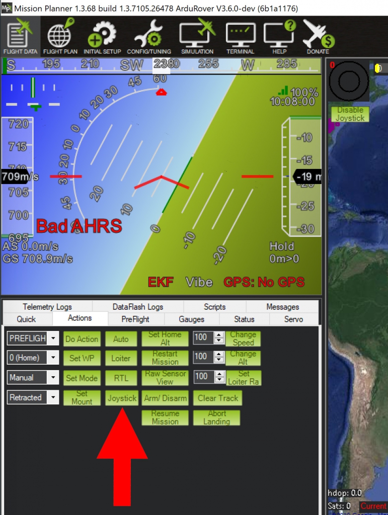
Note that we’re using the filter over in the lower right corner to hone-in on the PILOT_STEER_TYPE param - From the Mission Planner main screen, select the “Actions” tab in the lower-left-side tab group and click the “Joystick” button:
- From the Joystick popup window, click the “Enable” button at the top, ensure that the dropdown box next to “Ch 1” (near the top) has “Y” selected, and check the “Reverse” box to the right of “Ch 1”, i.e.:
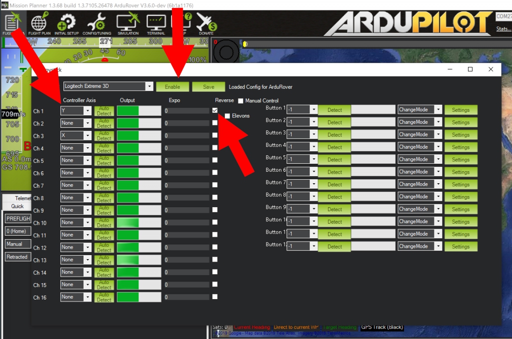
Don’t forget to click the “Save” button near the top before exiting this screen.


Now assuming that all goes well, you should see the green bar next to “Ch 1” grow when you push the joystick forward and it should shrink when you pull the joystick back. When the joystick is at rest the bar should be in the middle.
Setting your ArduPilot Flight Controller to Manual Mode and Arming it for Action
Now that the joystick is configured within Mission Planner, we’ve got a few last steps to complete to be able to control the Wingxine servo with our joystick.
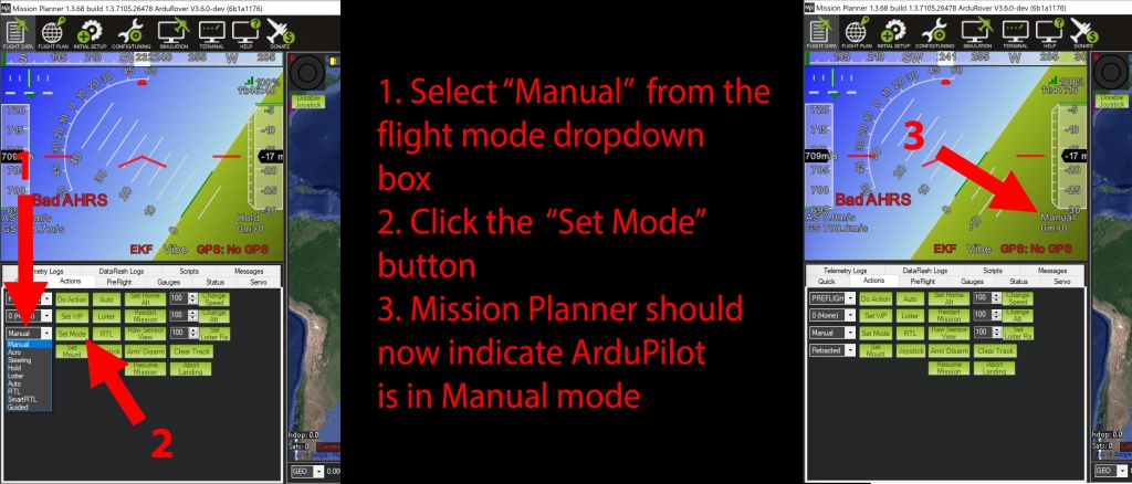
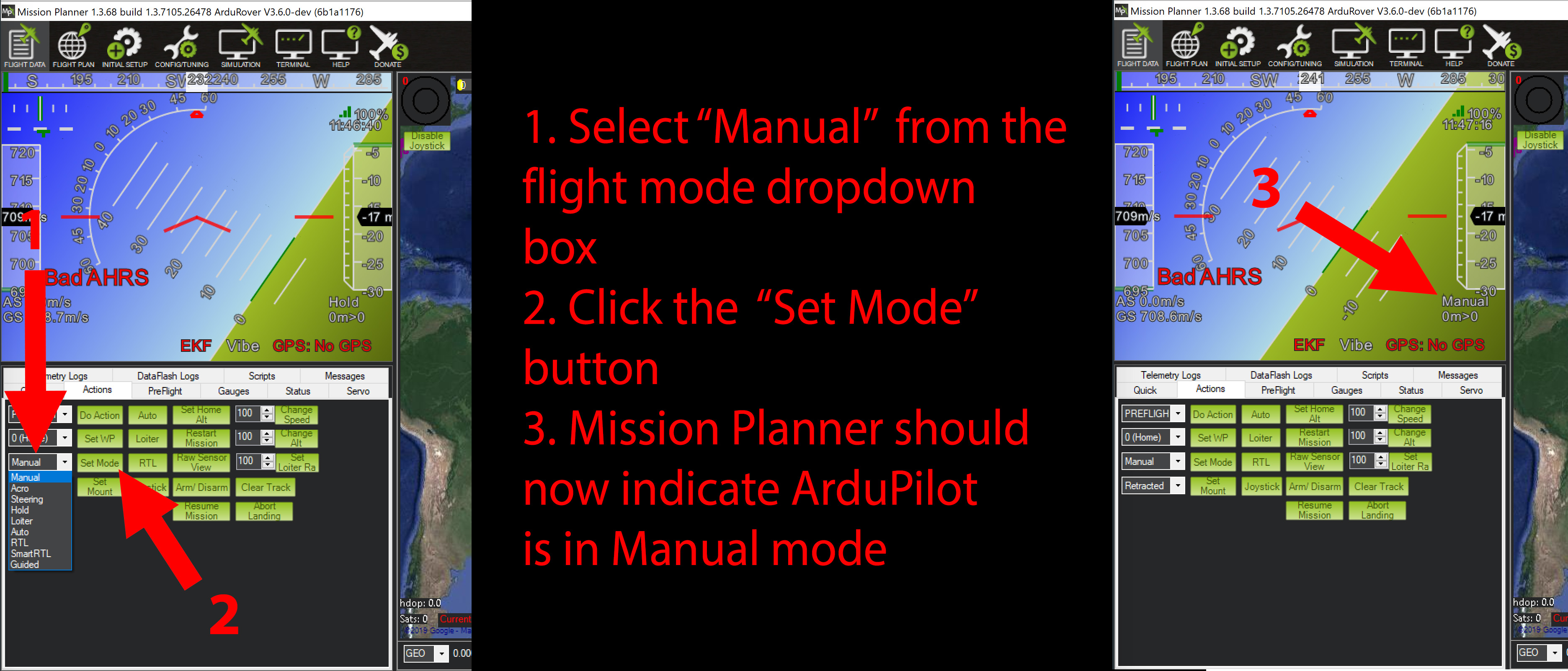
- Set the flight controller to Manual mode (for joystick control) like this:
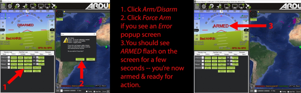
- Arm the flight controller by clicking the “Arm/Disarm” button, i.e.:

Now on the Mission Planner main screen, click the “Status” tab in the lower left tab box group and scroll over until you see the value of “ch1out”. Now when you push the joystick forward and backward you should see the “ch1out” value move between 2000 and 1000, i.e.:
If your flight controller’s Servo1 output pin is hooked up to the Wingxine servo’s signal pin (i.e. like the setup in the big picture with the red 12v battery, the servo, et al earlier), then you should now be able to turn the servo plate by actuating the joystick.
Dialing-back the Wingxine Servo to the Maximum Safe Range
Now that you’re controlling your Wingxine servo with a joystick connected to Mission Planner, it’s time to scale back the servo’s range so that it’s approximately 150° (maximum) — much more on the reasoning for this in a minute. Let’s go ahead and drop a video showing you how to make that adjustment and prepping you for the discussion ahead:
If you watched that video, did you notice how, by good fortune, the travel of the Scag right servo linkage is almost exactly 33 millimeters? So for the Scag, using the holes in the servo plate provide exactly the amount of horizontal travel needed to move the mower handle throughout it’s entire range of operation. Note that, even though we have the full range available, on our current setup with the big Scag we’re limiting the forward throttle to approximately 60%. The reason for this is that, in the event of some unexpected failure, I’m not yet wanting the Scag barreling down on someone at 10 MPH.
Now that we’ve thrown around this 33-millimeters-of-travel number a few times, it’s probably appropriate to make another corollary observation: if your setup needs more than 33 millimeters of travel, then you don’t need to use the holes on the Wingxine servo plate. You’re going to have to put on your engineer cap and figure out a way to extend off that plate a little so that your control arm doesn’t end up pulling the Wingxine servo into a parallel-with-the-servo-shaft nightmare scenario.
Since we’ve broached the nightmare scenario topic, let’s take a moment to dig in on that a little more deeply before proceeding.
A Soothsayer Bids You Beware 3 O’Clock and 9 O’Clock
Remember that we’ve got 1 cardinal rule for the servos — they must be overridable by an average-strength person in any reasonably imaginable scenario. And remember that I’ve postulated that the Wingxine servos and the linkage we’re employing are overridable — but there’s one big land-mine that you must be aware of lest your mower become HORRIFICALLY STUCK IN FULL-SPEED FORWARD OR FULL-SPEED REVERSE.
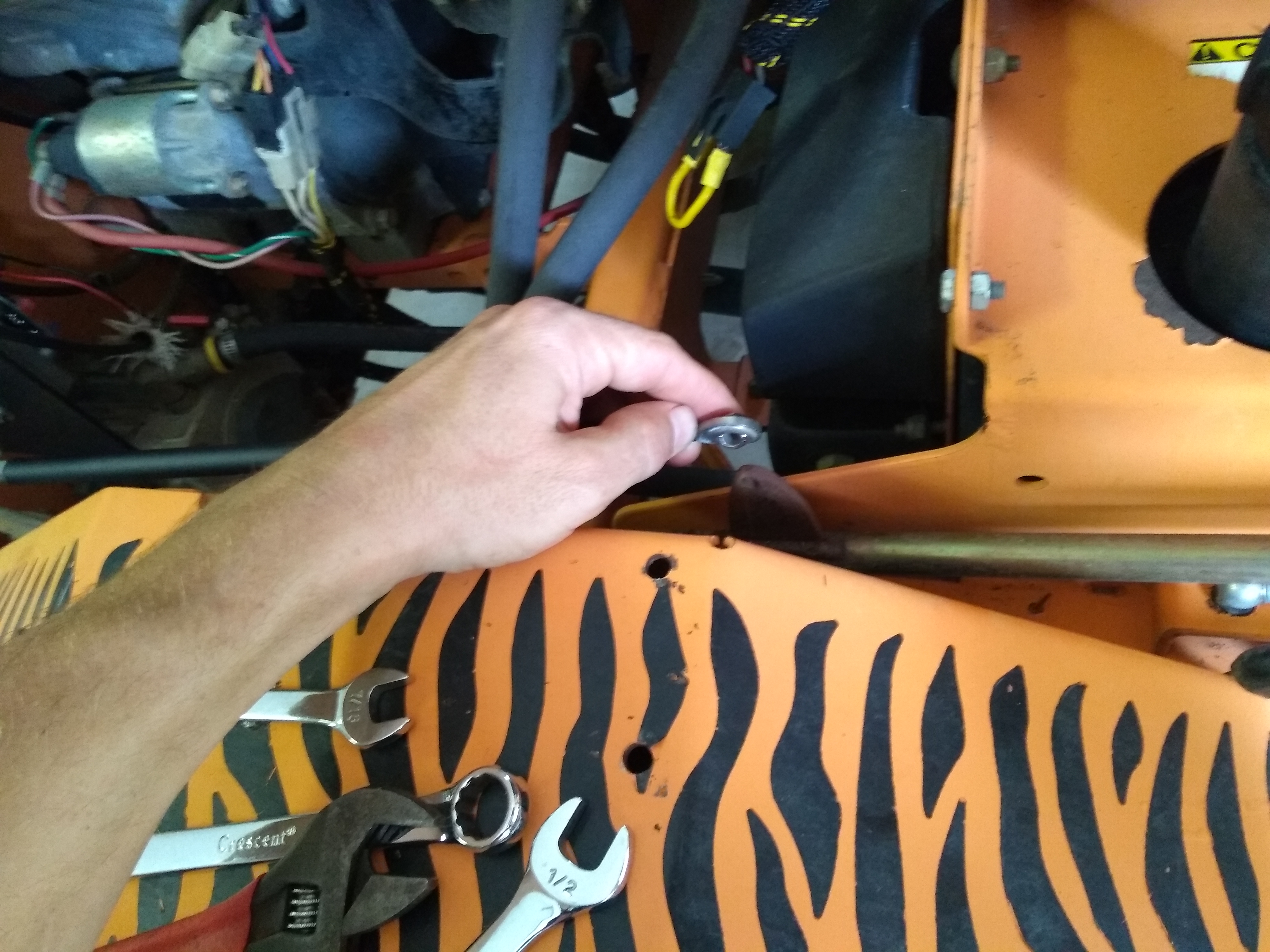
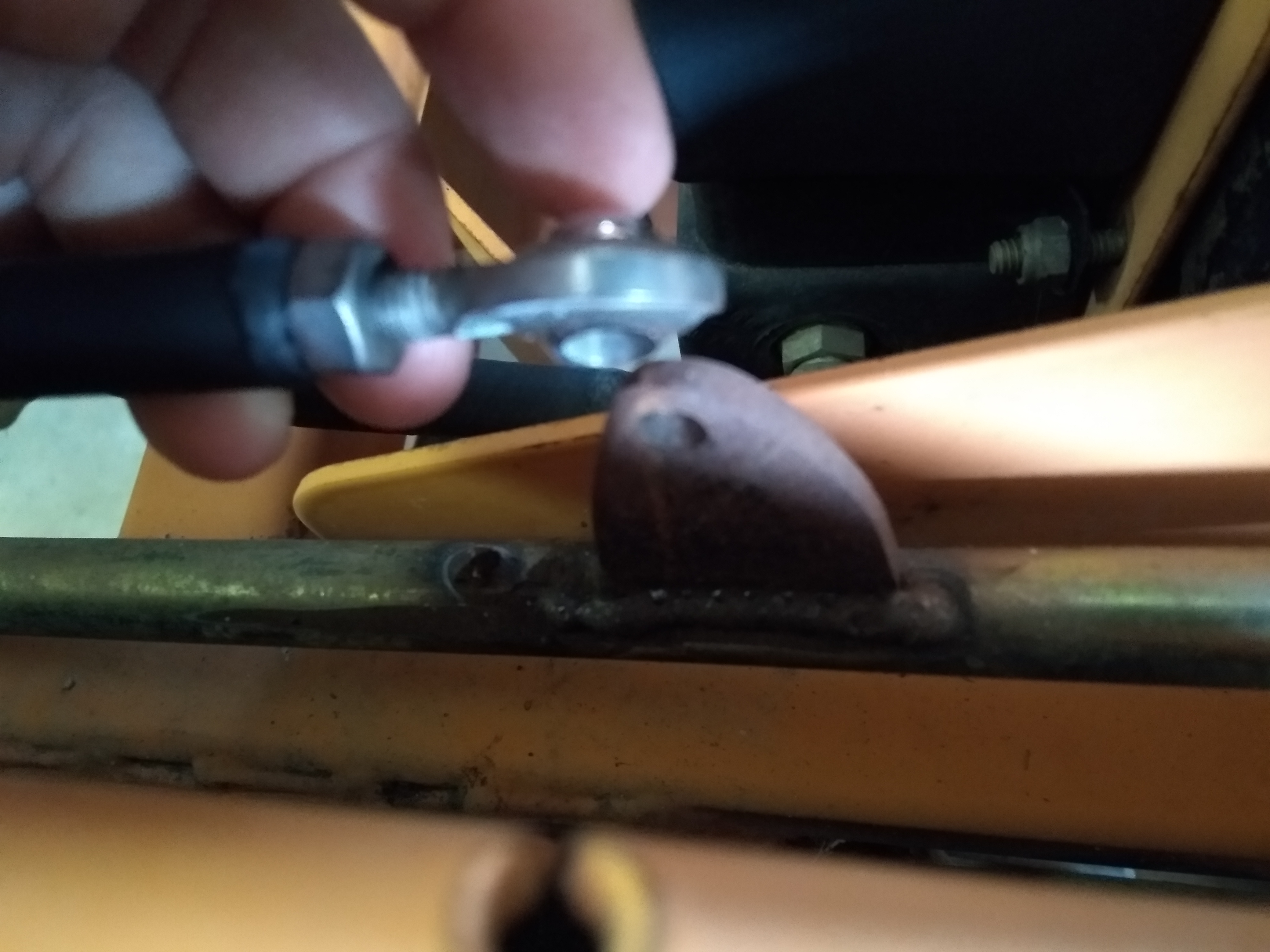
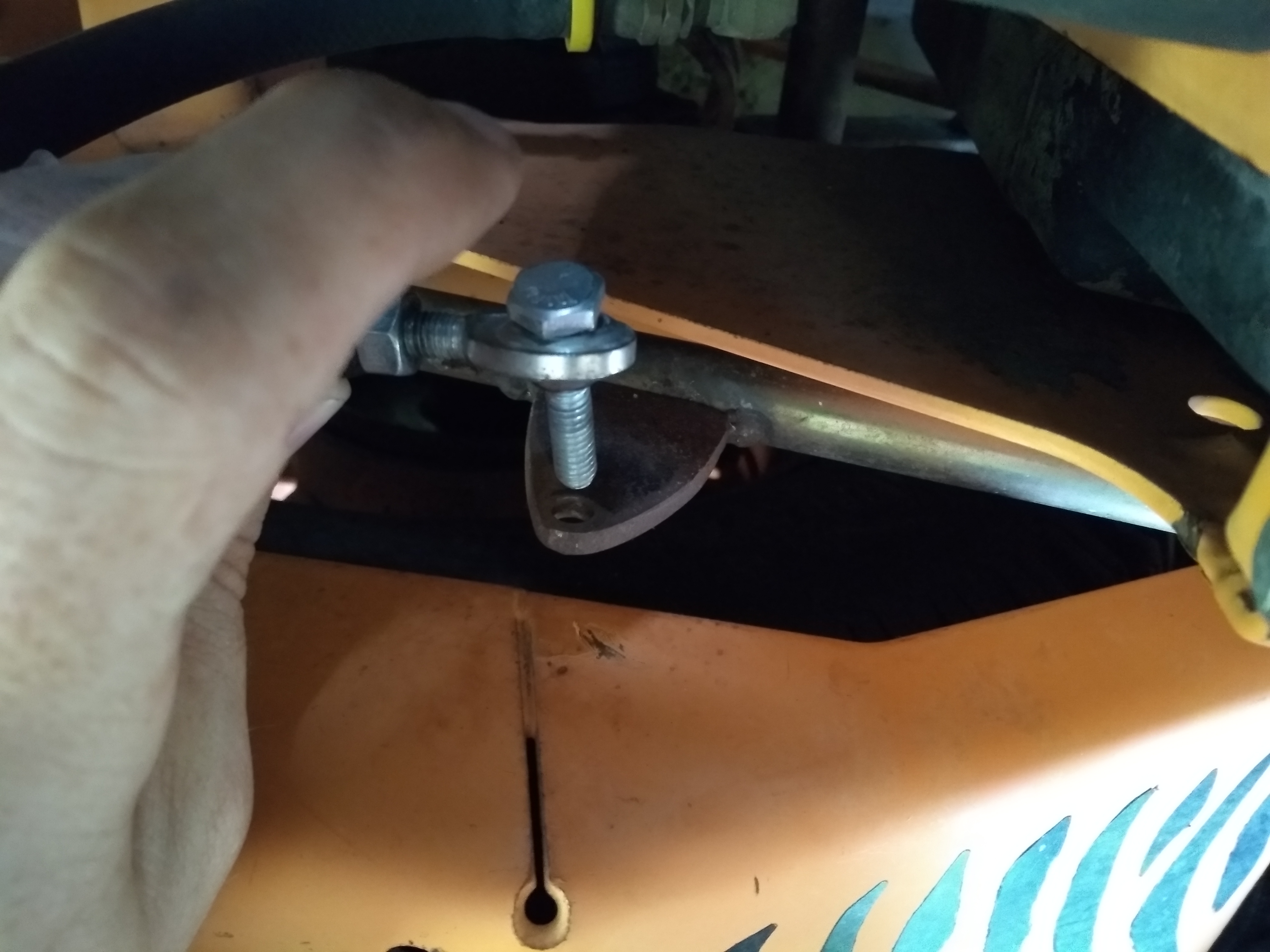
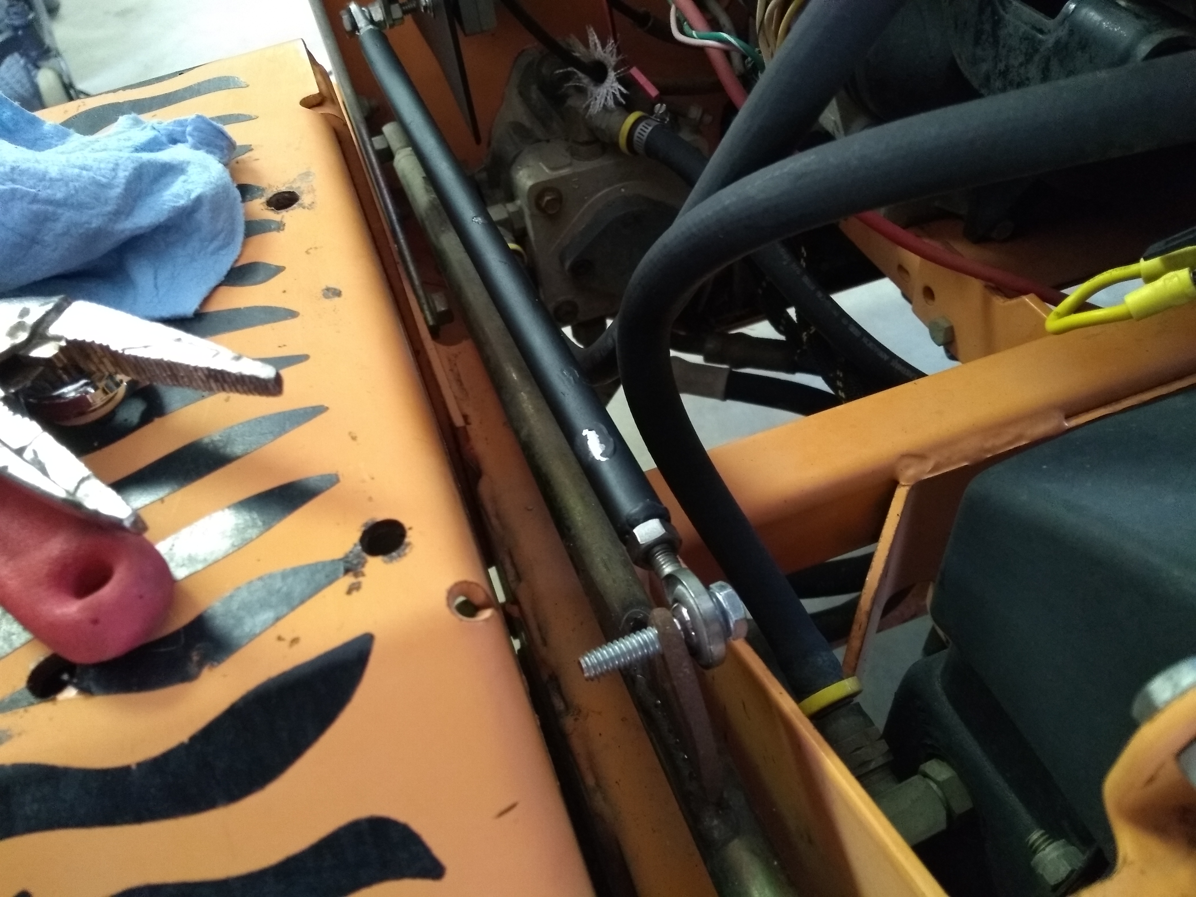
We’ll get to some pictures of the nightmare scenario in a bit, but first take a few seconds to peruse the collection of photos below showing our servo linkage configured in a manner that should be easily overridable.
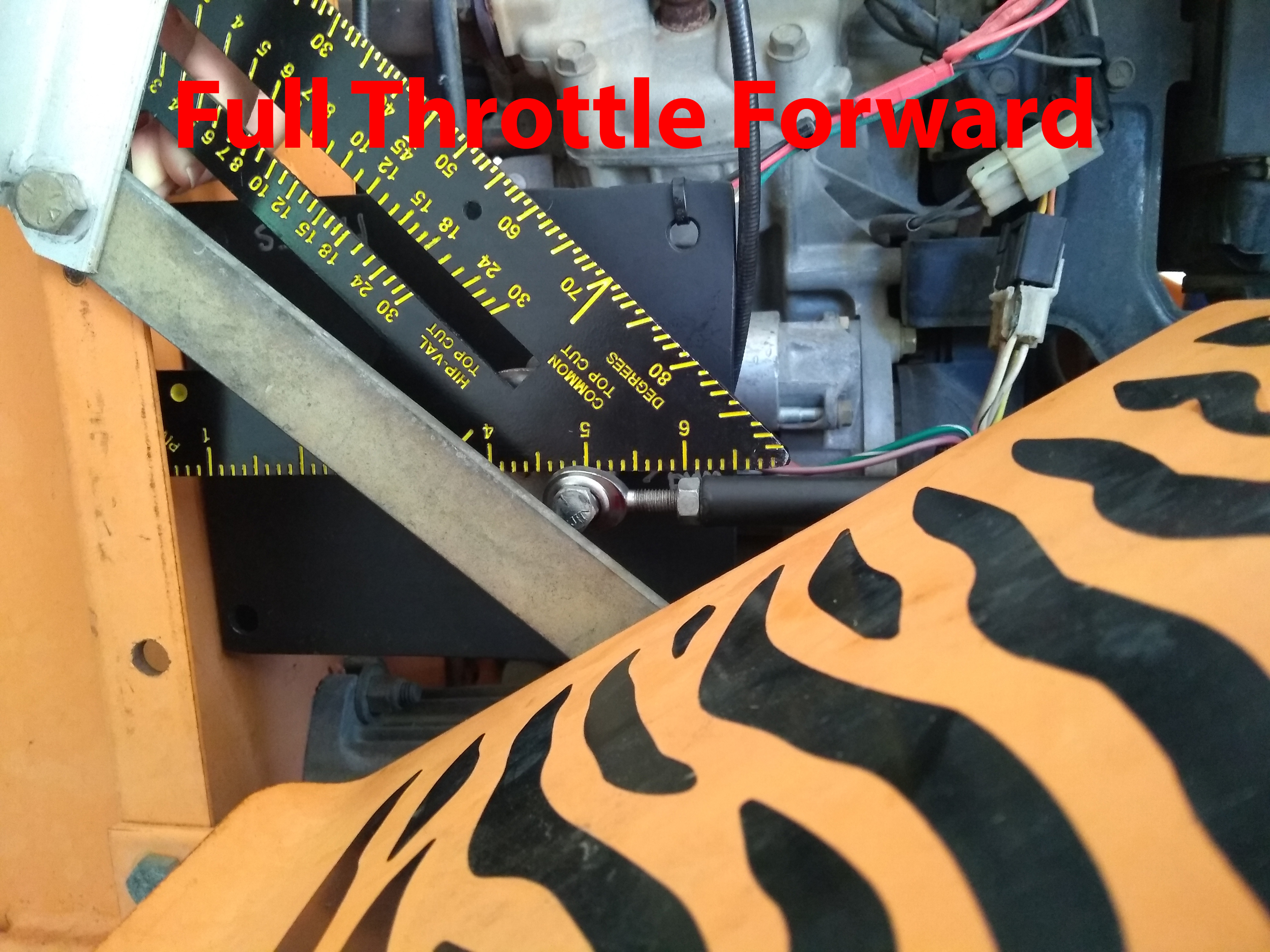
Here is the right-side servo linkage at full throttle forward and full throttle reverse:
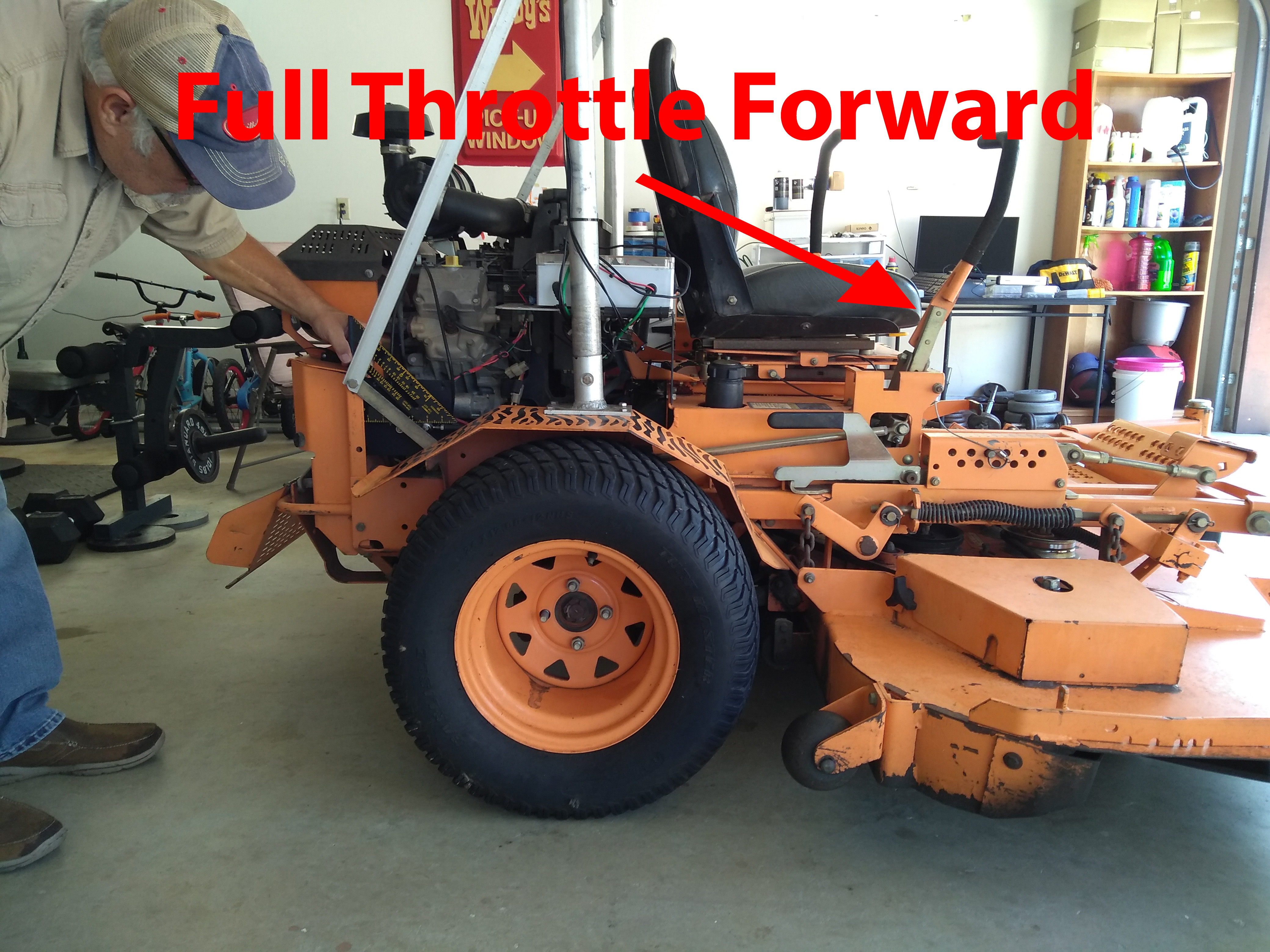
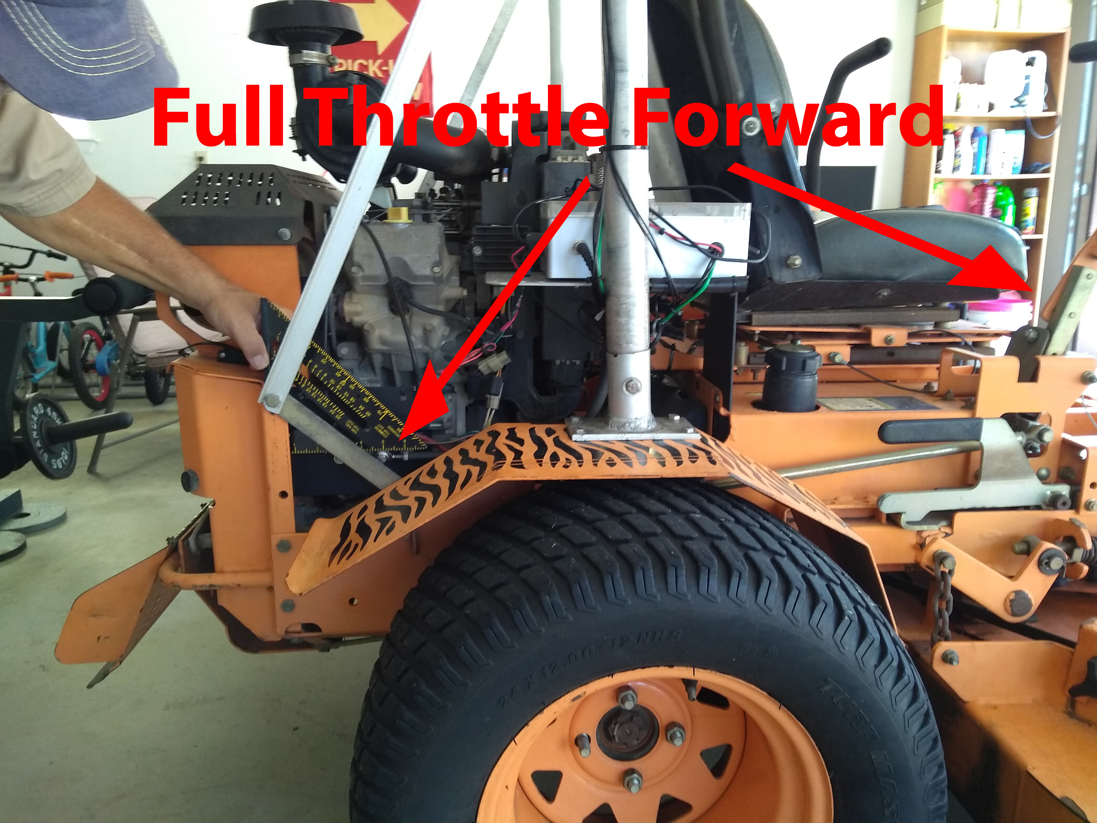


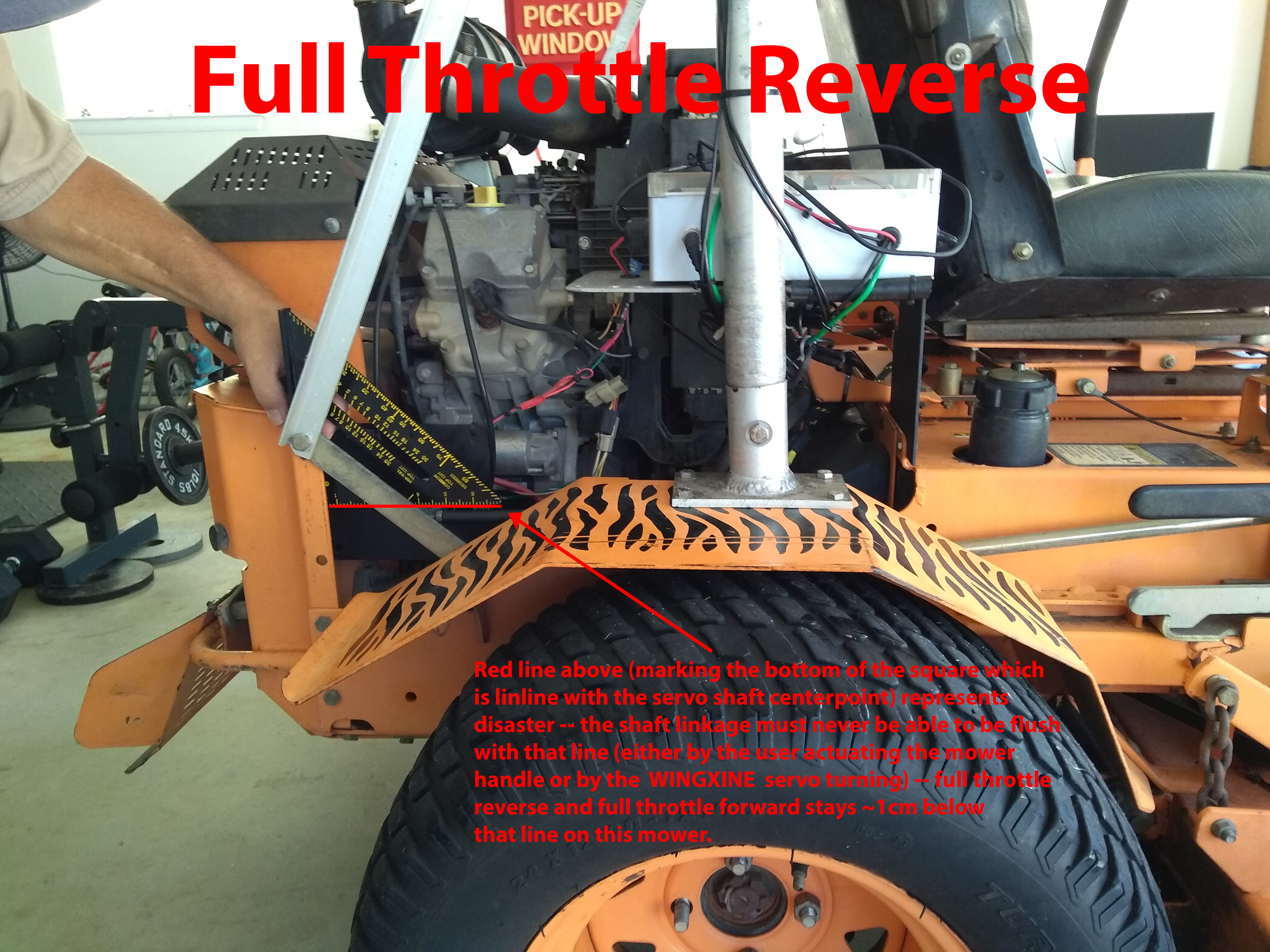
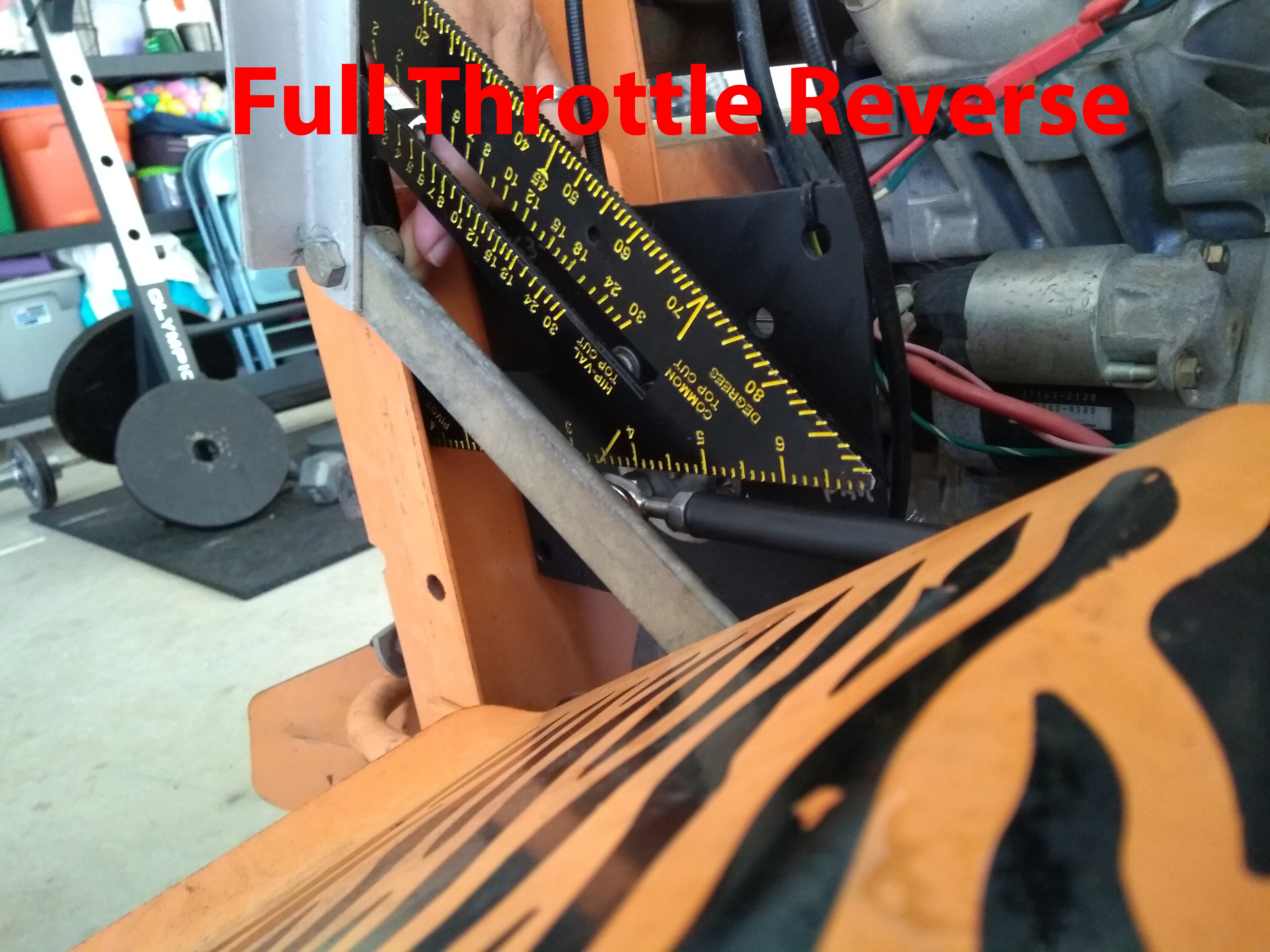
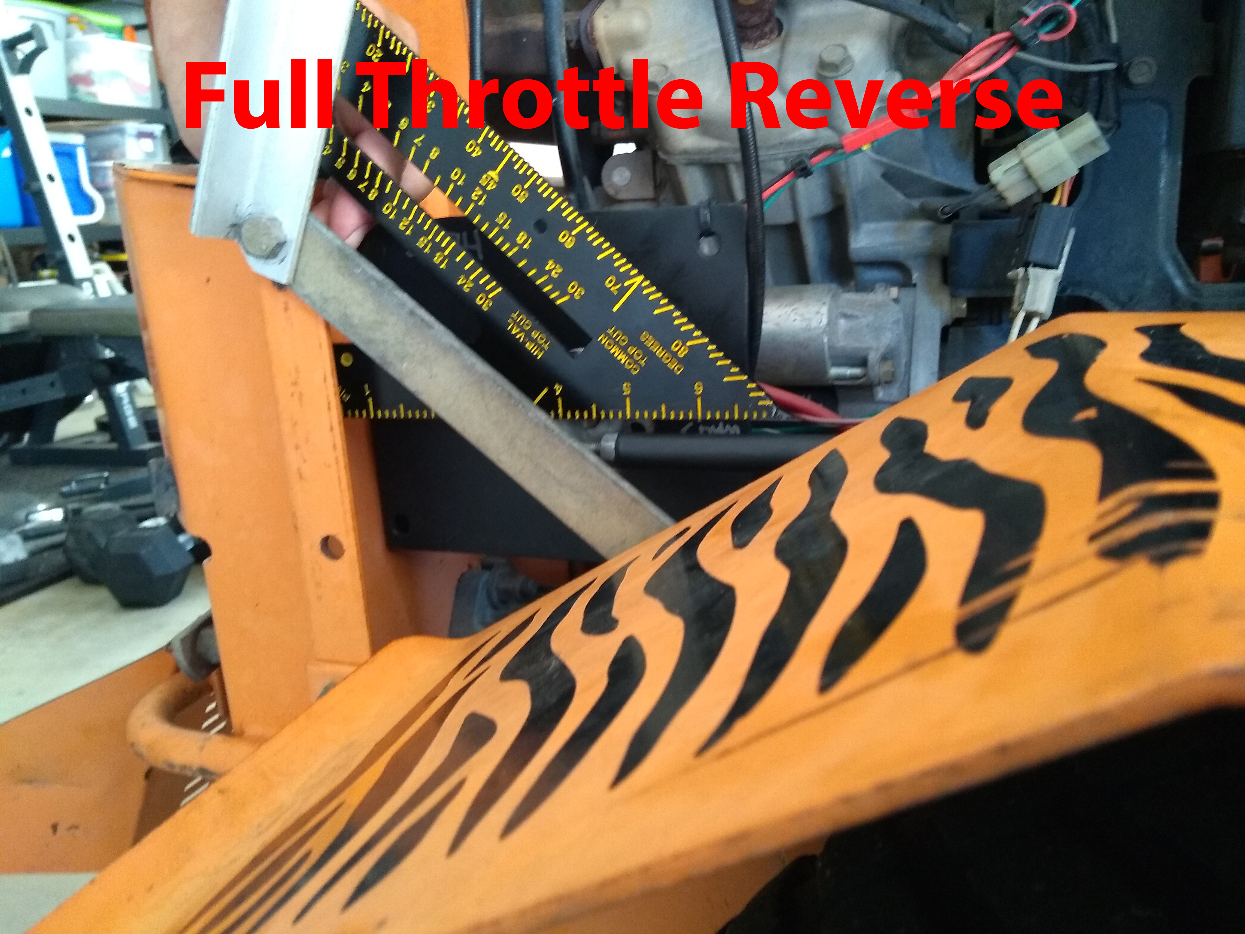
Here we show the left-side servo linkage at full throttle forward and full throttle reverse:

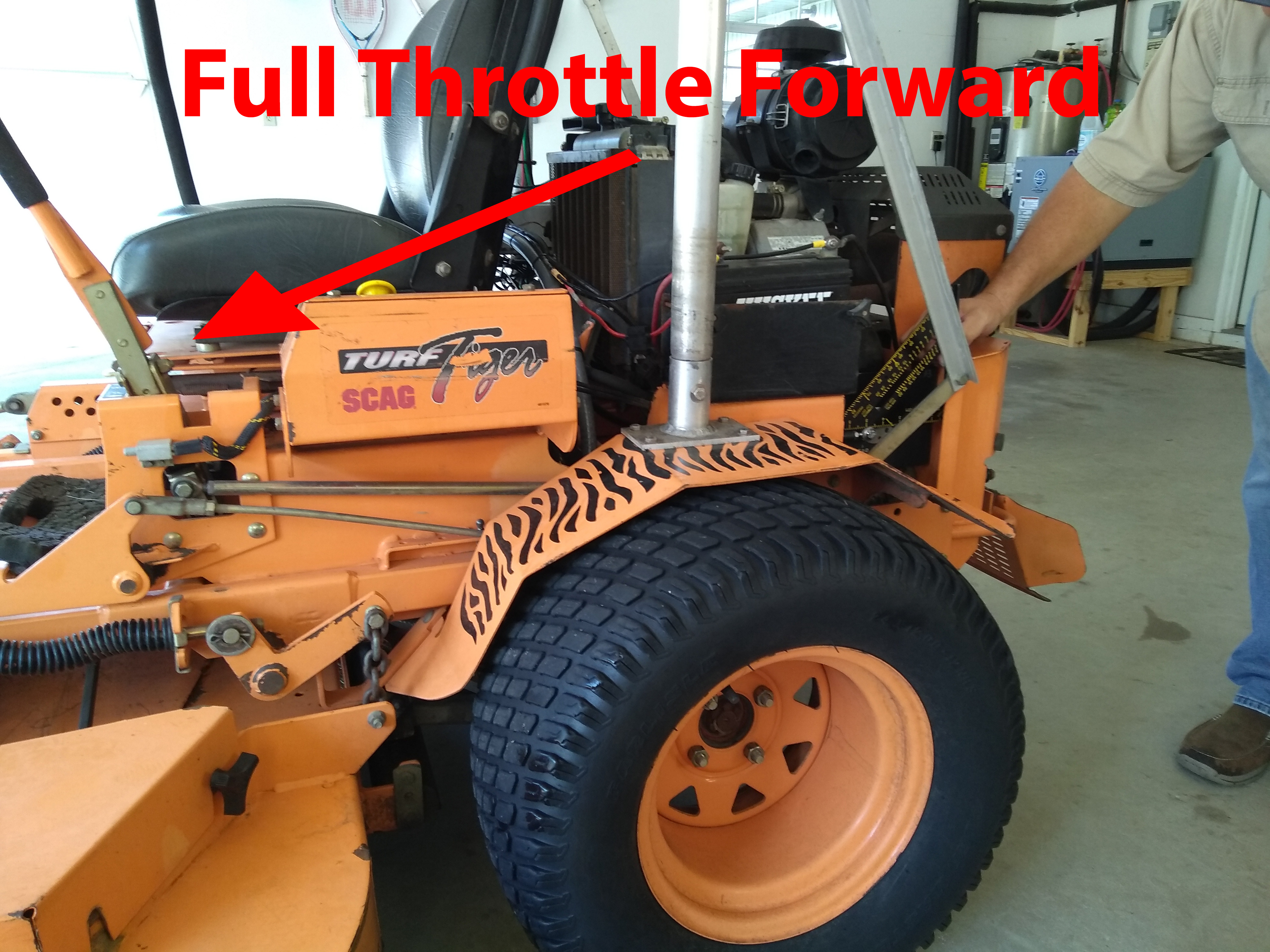
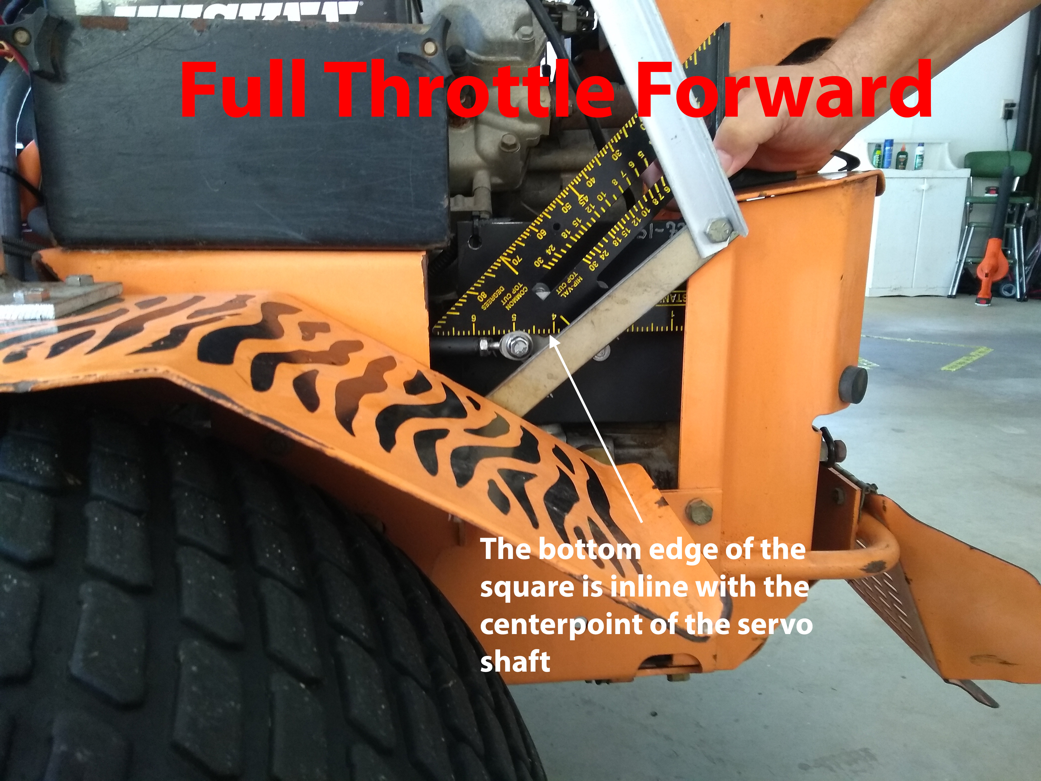
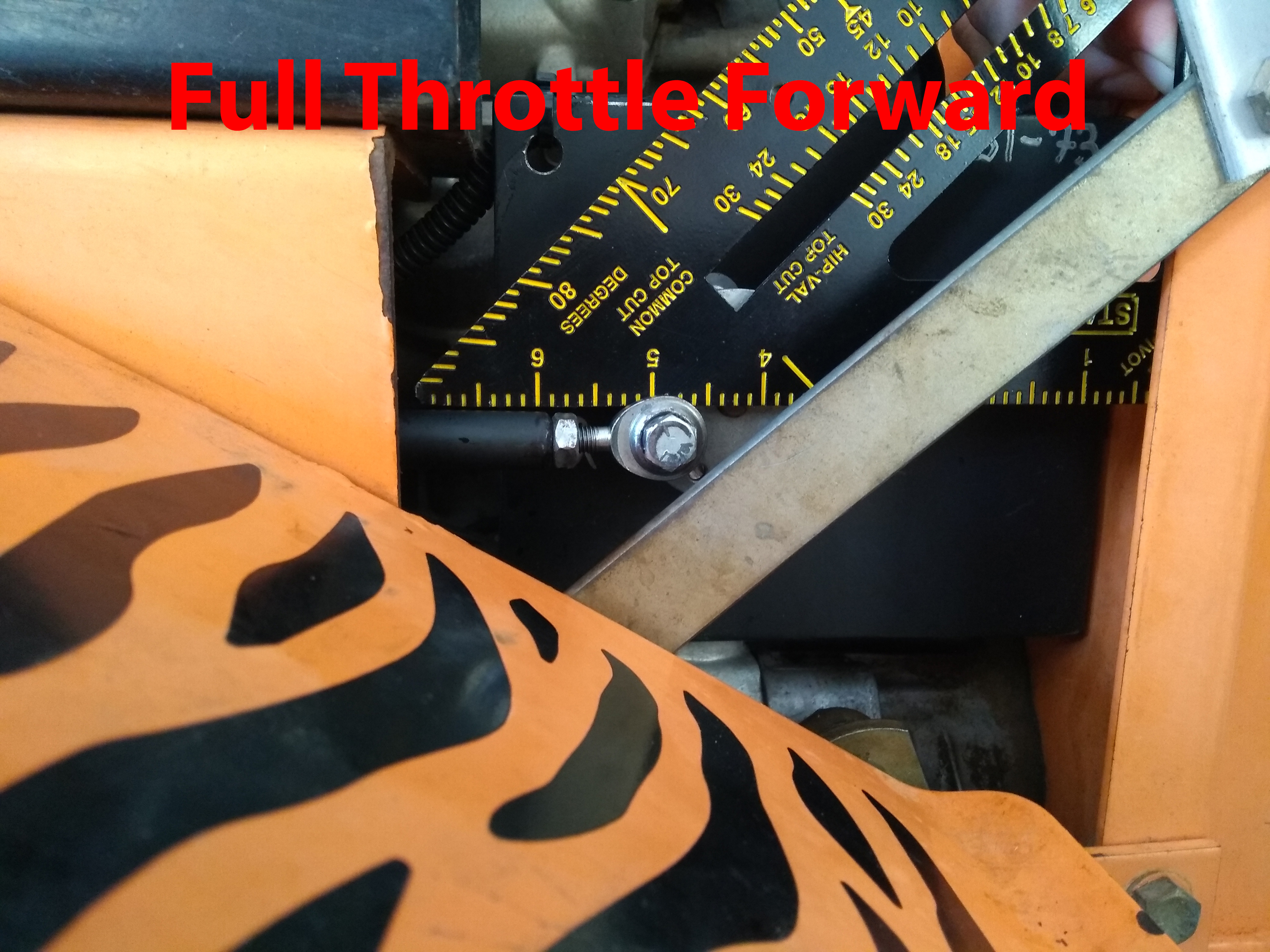

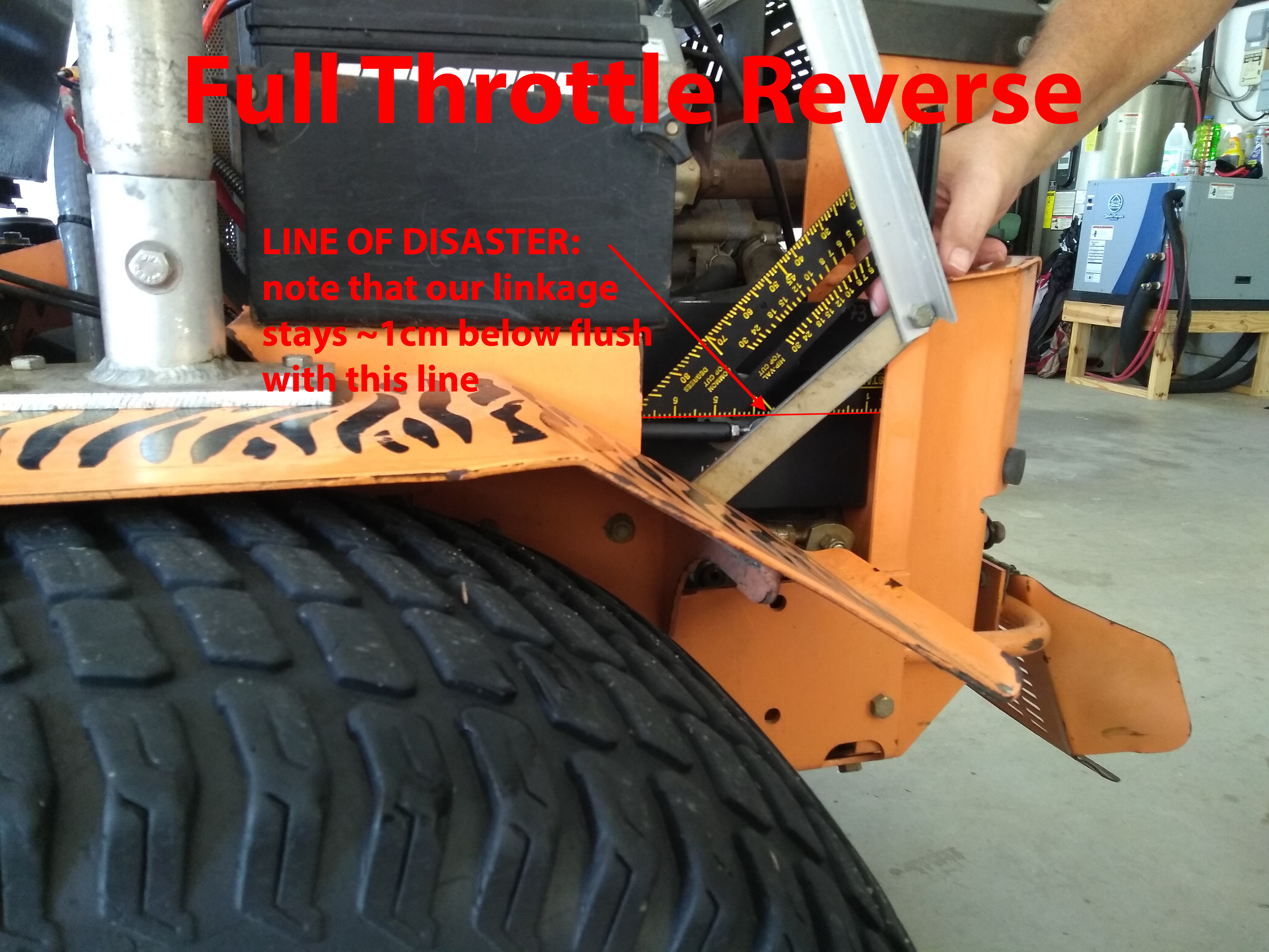
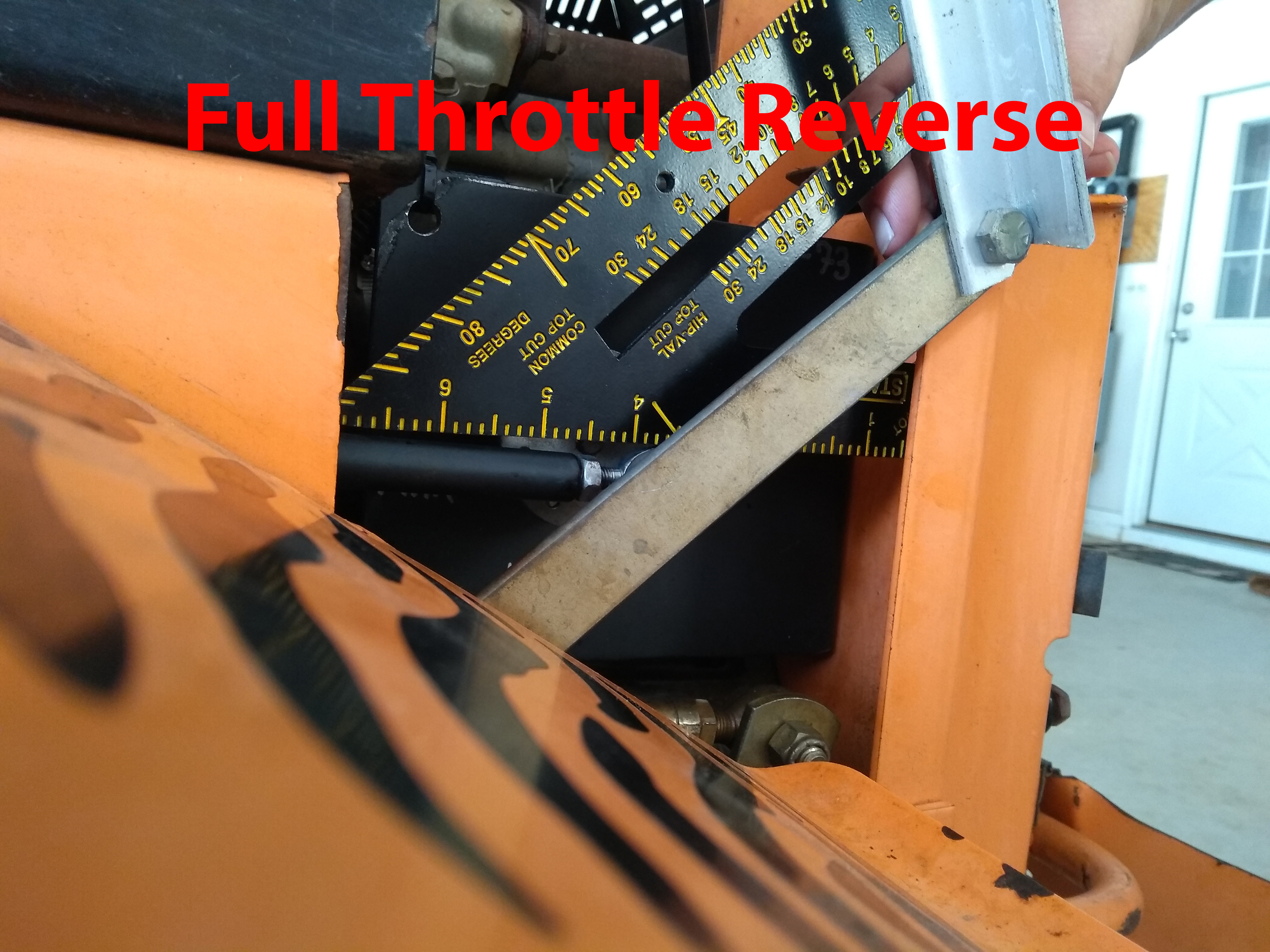
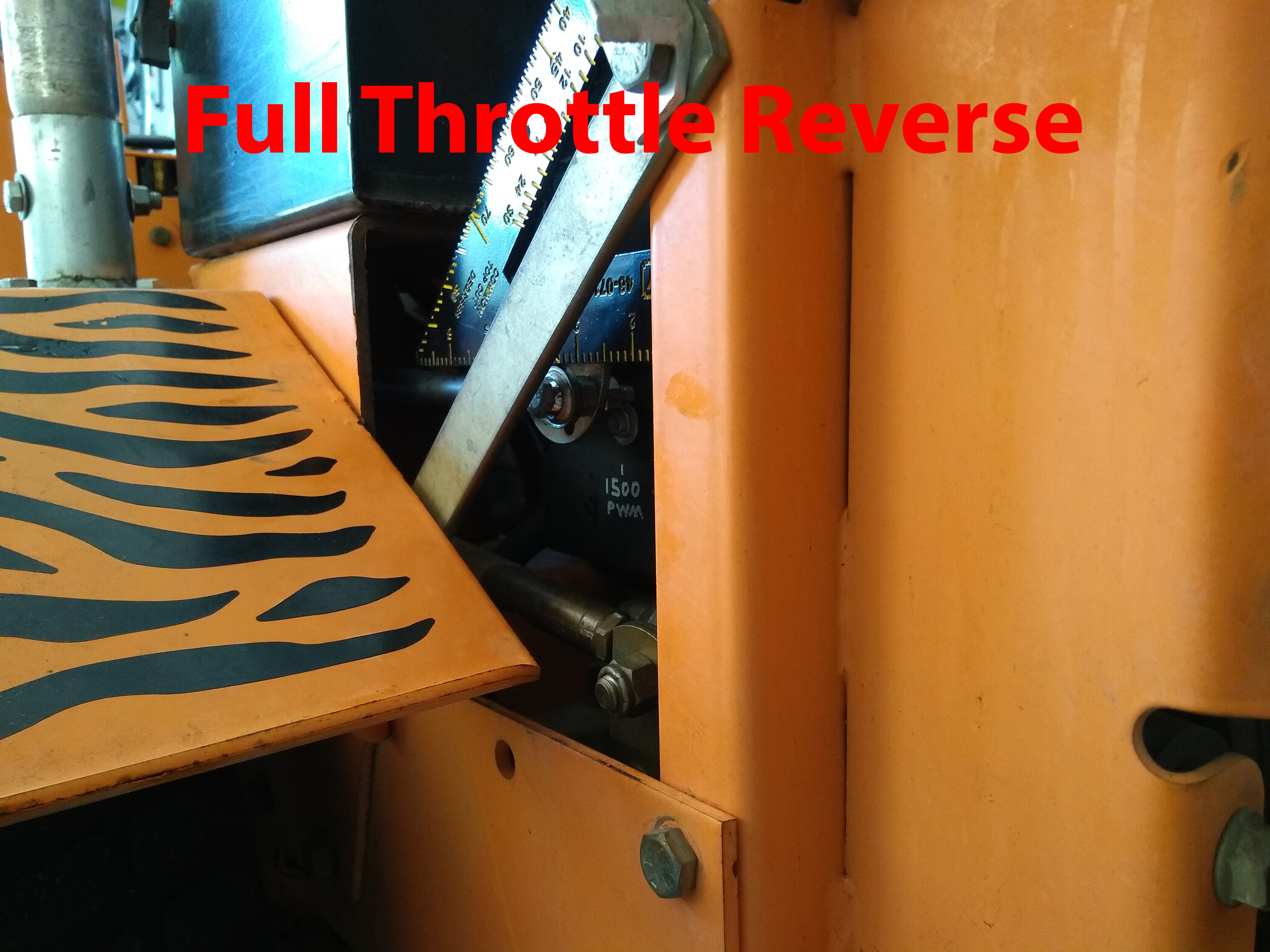
The full throttle forward and reverse linkage pics above reveal that the servo linkage stays safely below the parallel line of the servo shaft (shown by the bottom edge of the black square) throughout the entire range of motion. In other words, the force vector of the linkage is never entirely directed into the servo shaft — we always want there to be a component of the linkage’s force vector that’s pointed down (or up, depending on your configuration — the point is you never want to be in a place where pulling or pushing the mower handles sends 100% force directly into the servo shaft) so that our pushing or pulling the mower handles will result in the servo rotating (well, here again this description seems clunky, but hopefully the pictures below show you what to AVOID).


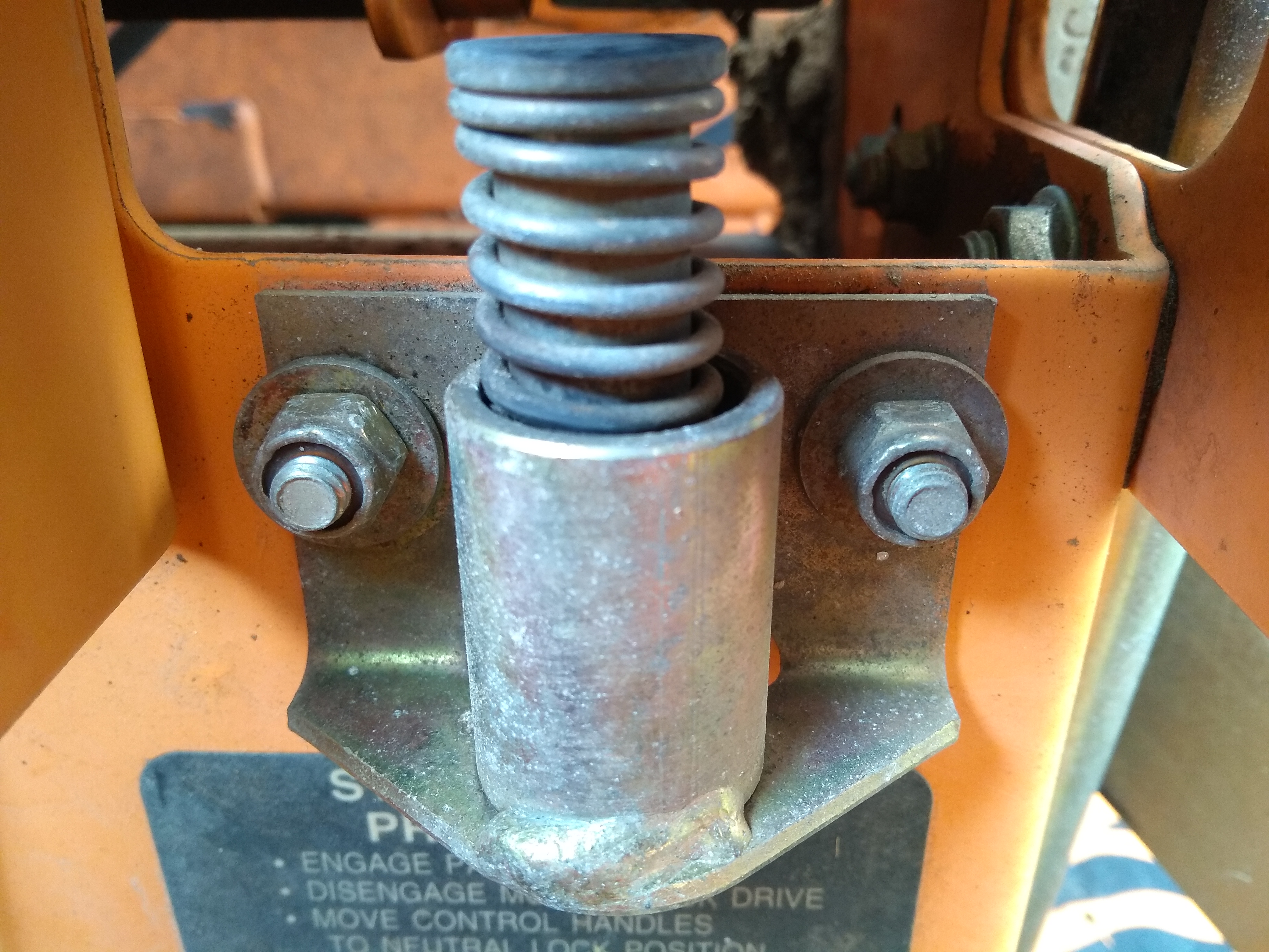
Here are several different angles of these two linkage positions you must ensure CAN NEVER happen (either by the user actuating the mower handles or by the servo rotating to some demanded position):
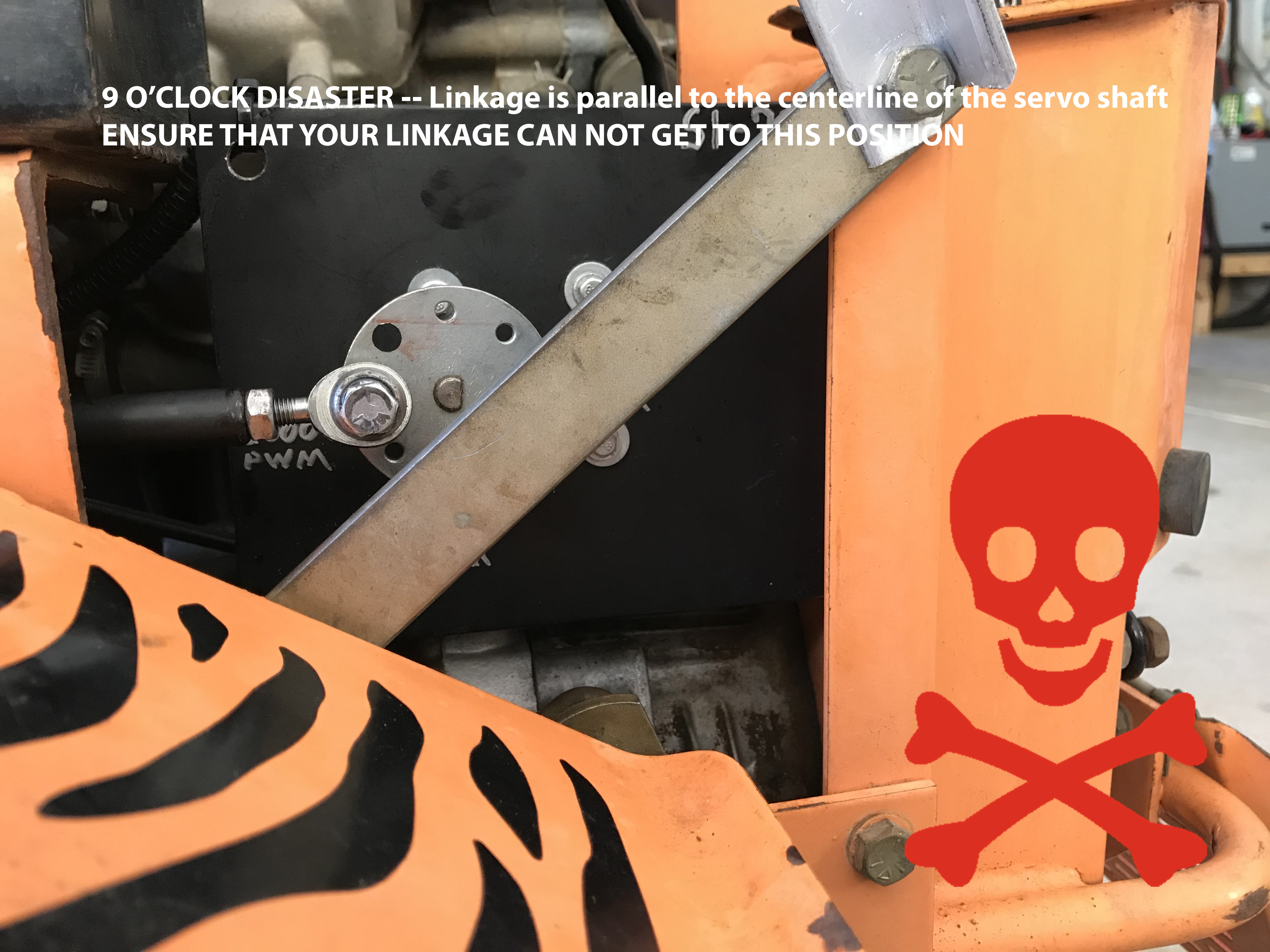
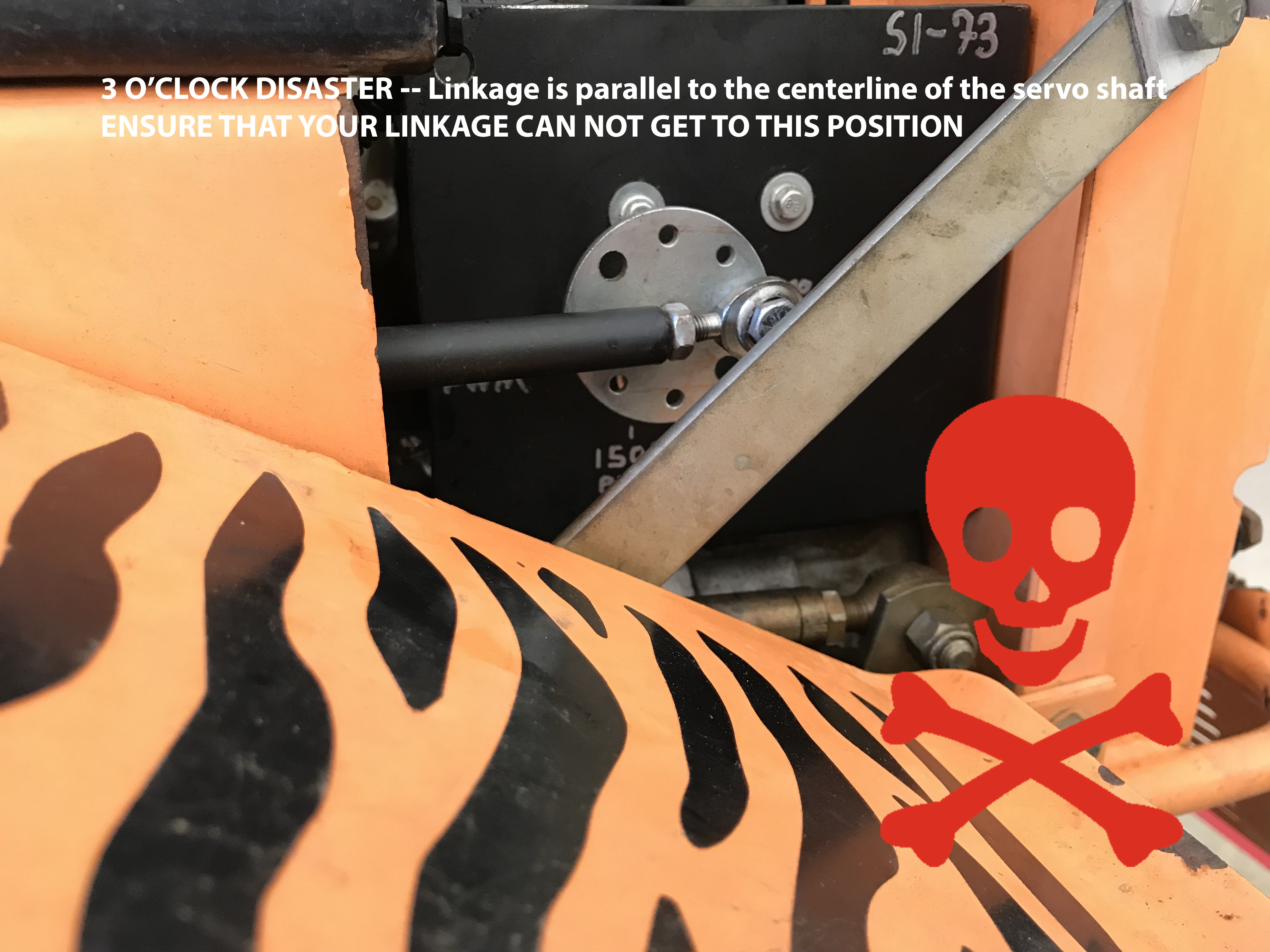


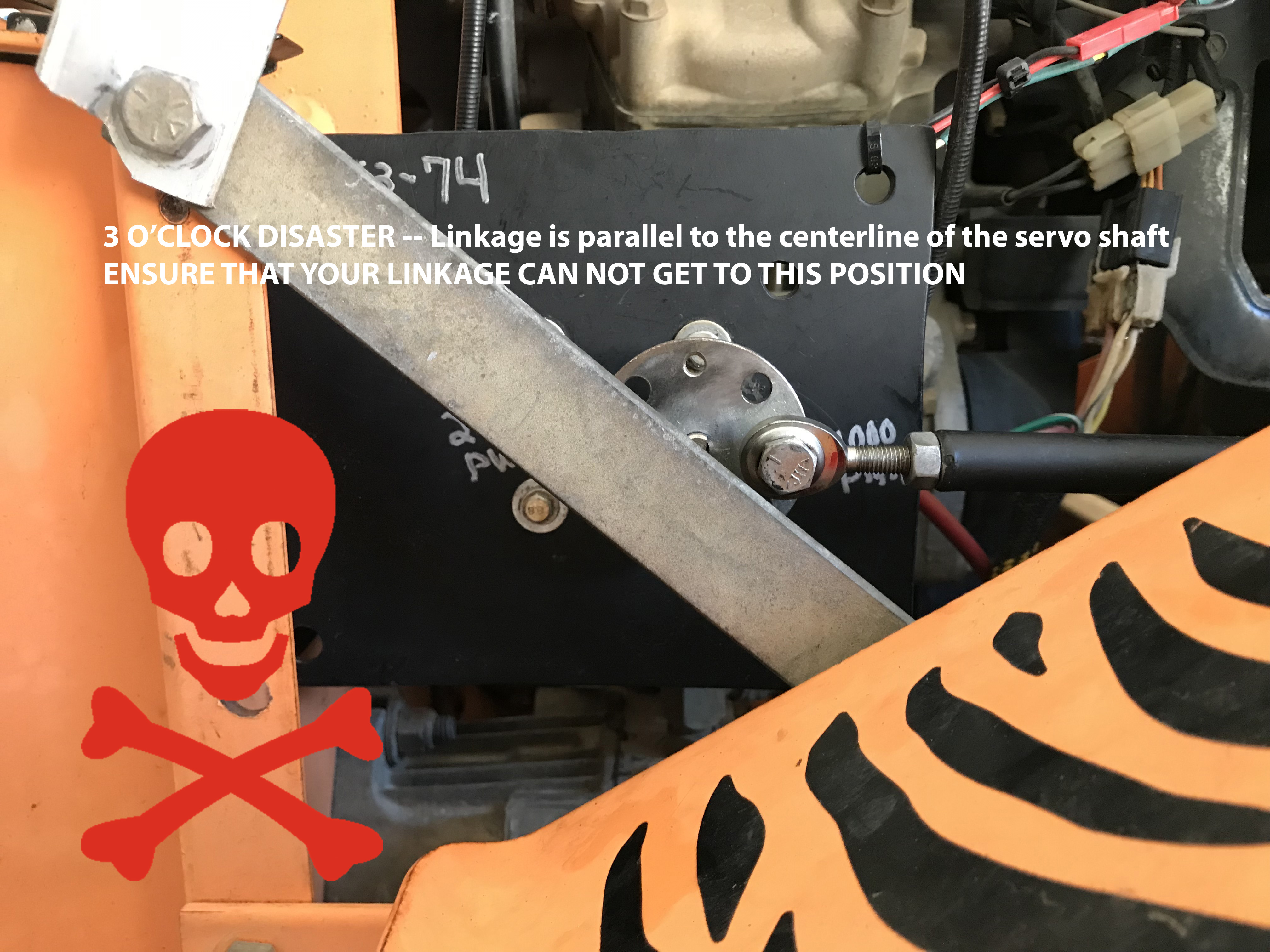
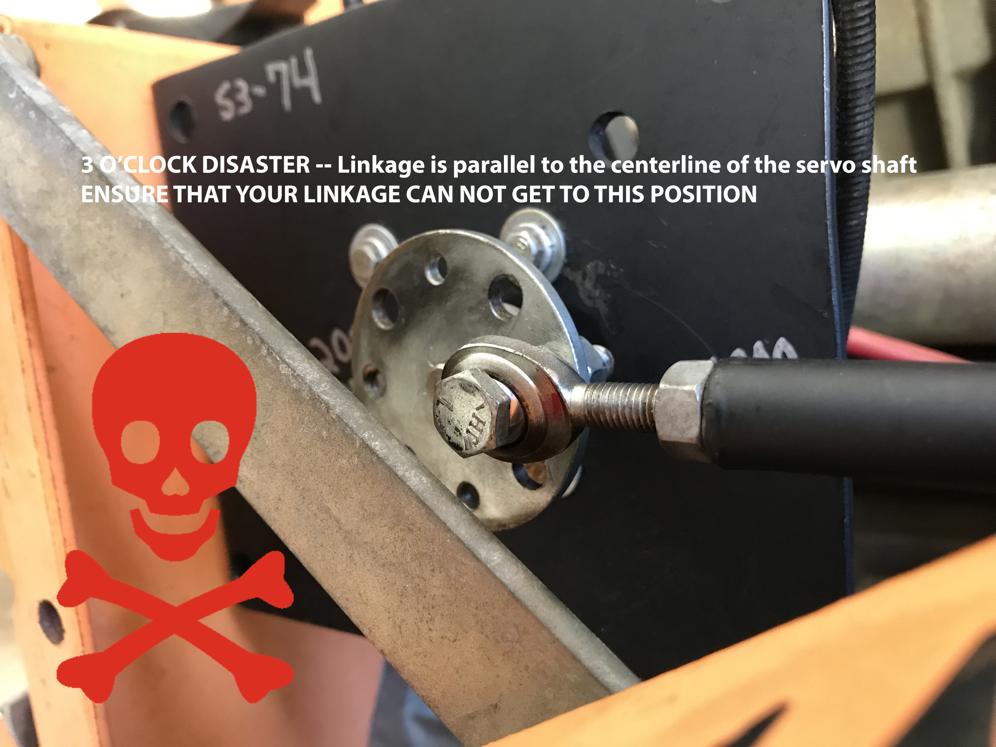
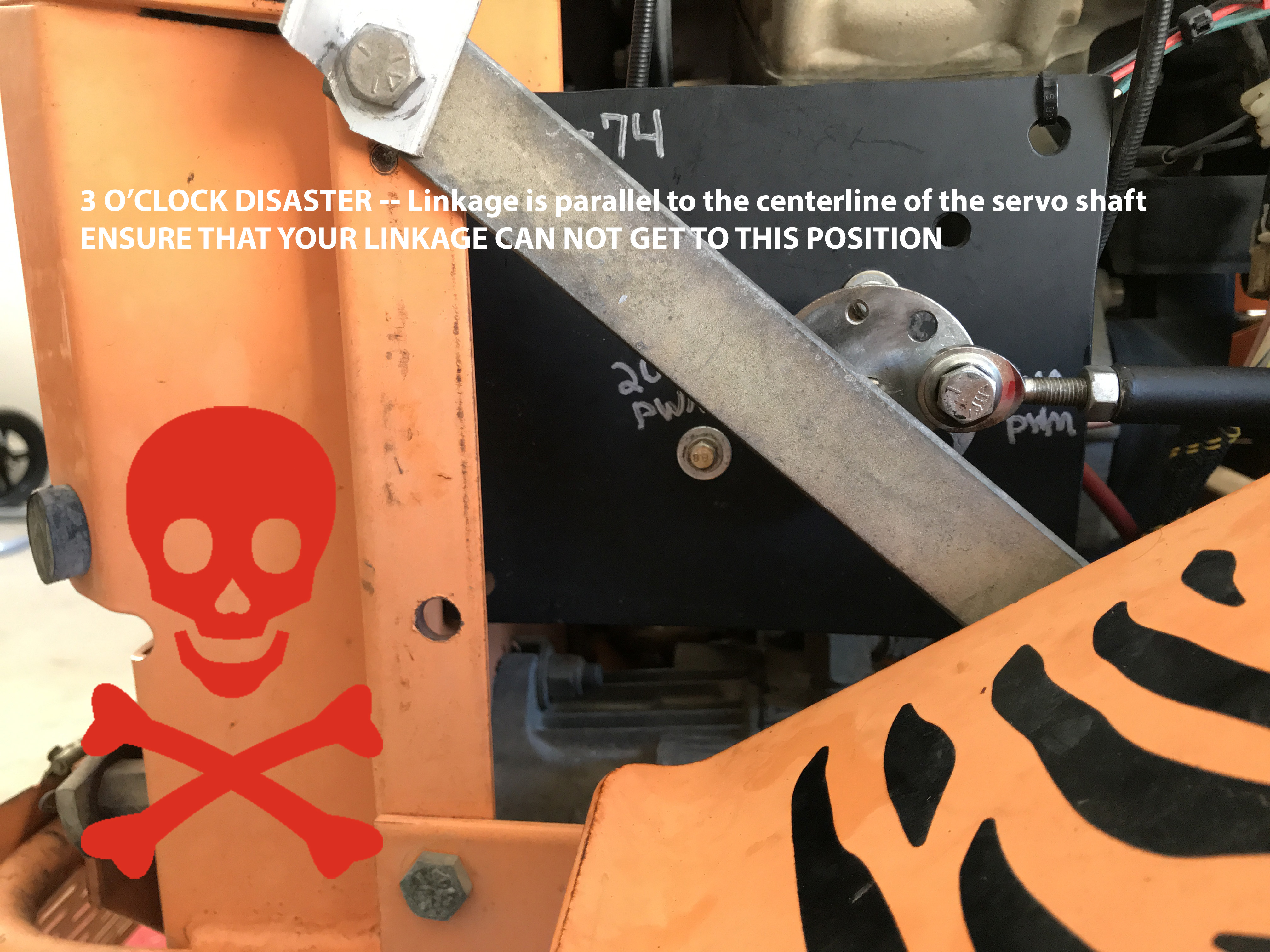
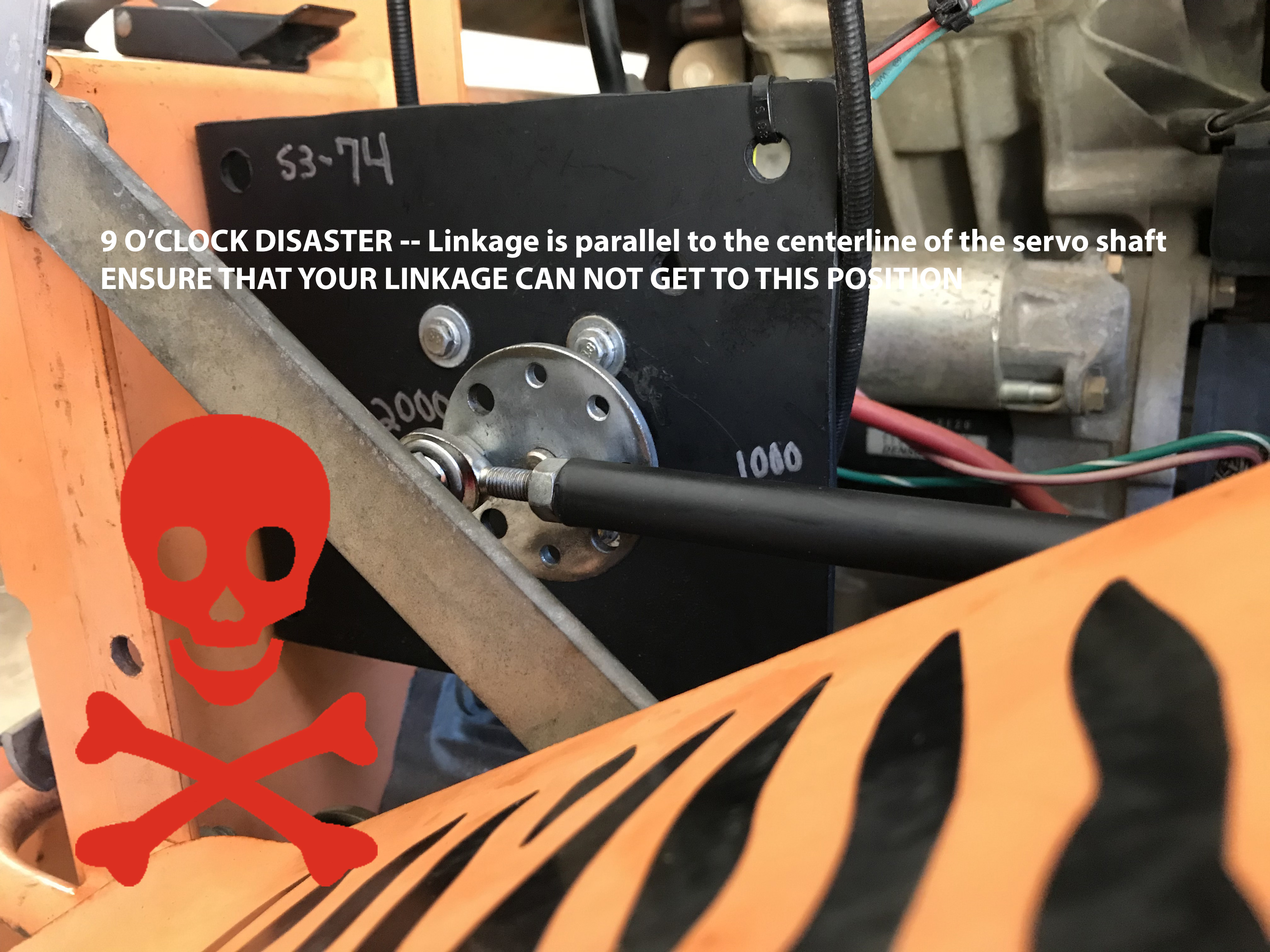
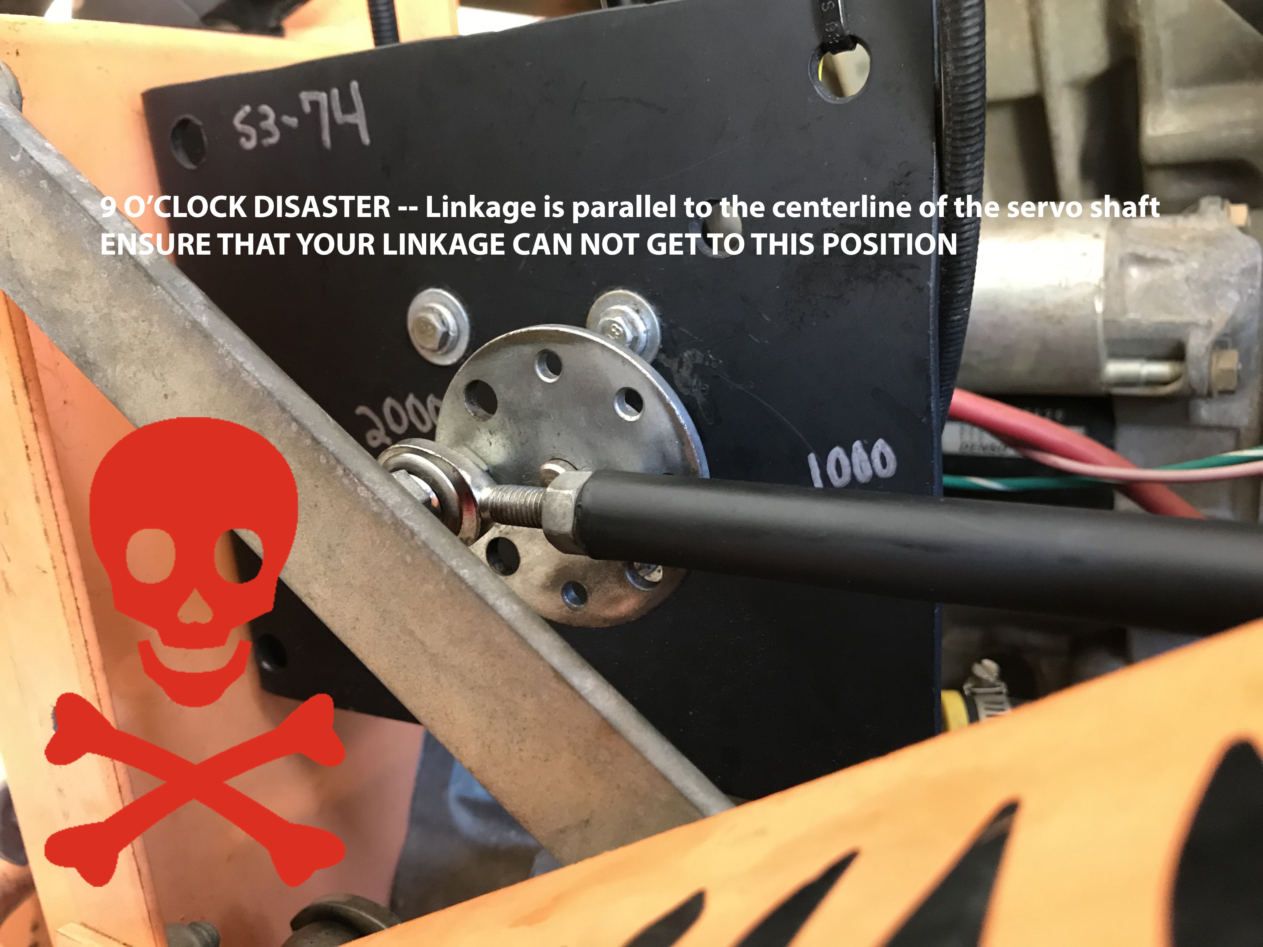
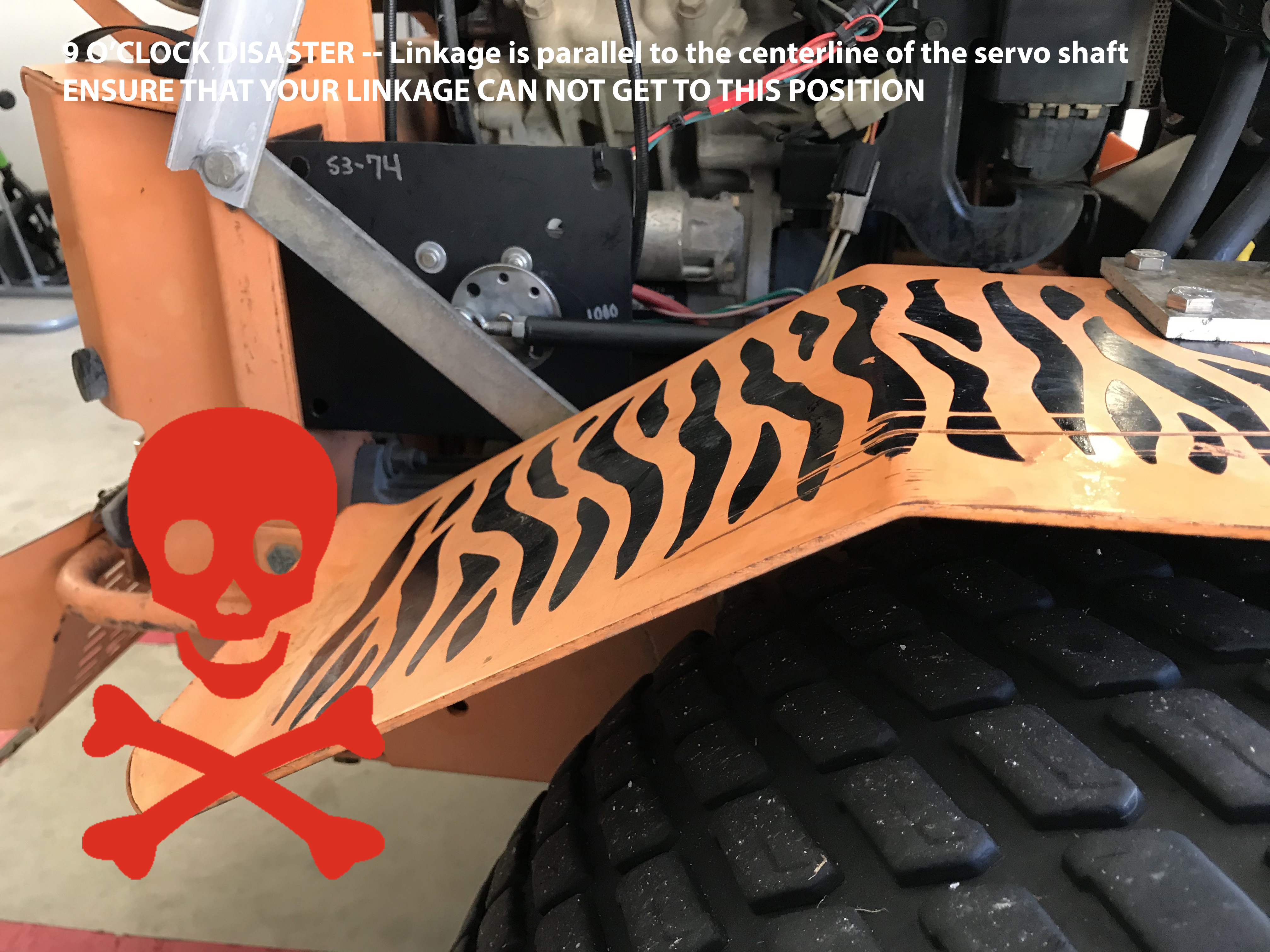

If your servos can get to points where the force vector of the servo linkage is directly inline with the servo shaft, you are courting disaster.
If anyone reading this is actually planning on using the design above, I would humbly ask the following: as an exercise, please turn on your Wingxine servo, bump back the shaft angle range so that it can rotate up to 3 o’clock or 9 o’clock, and give it whatever PWM is necessary to get to those 3 o’clock / 9 o’clock scenarios on your build — so just to be clear, now you have the Wingxine servo turned on and it’s holding the linkage parallel to the center of the servo. Now go ahead and try to move the mower arm back to neutral — not so fun eh? Imagine trying to move those handles out of that position in some unthinkable scenario when you’ve got no seconds to spare.
Fabricating the Servo Linkage Parts
There are 3 pieces to the linkage puzzle that you’ll need to fabricate:
- You’ll precision weld a 1/4-28 fine threaded nut (suggested in the parts list earlier) to either end of the 12″ steel rod (also in the parts list) to create the adjustable linkage shaft
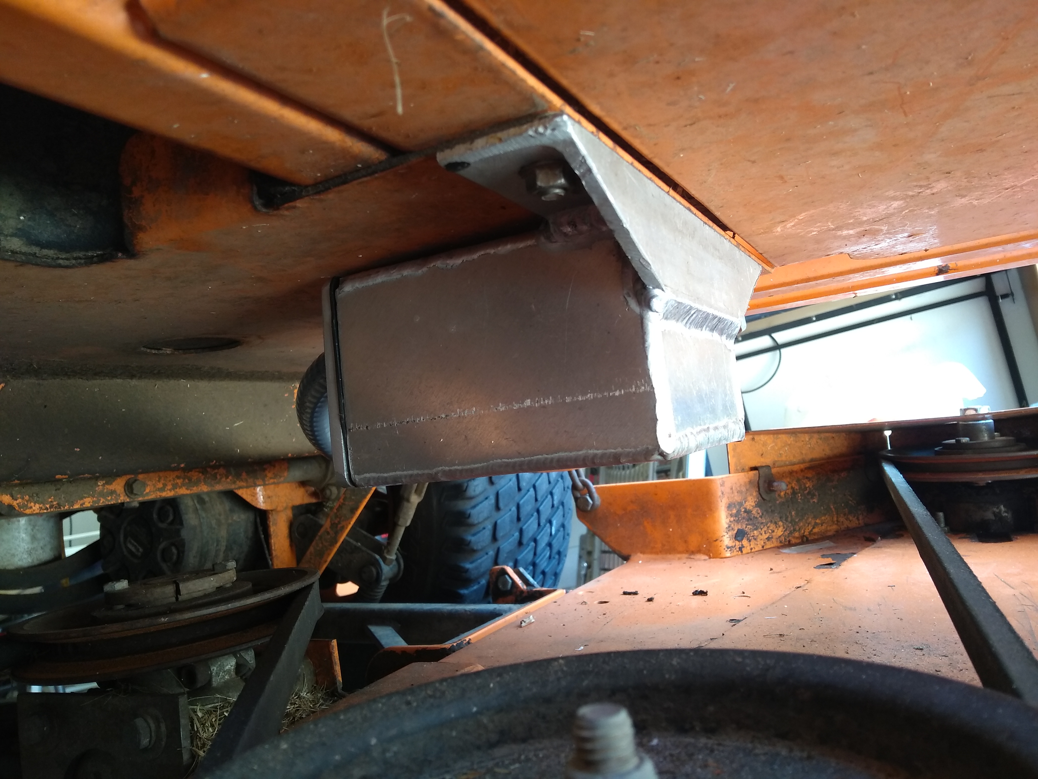
- You’ll cut out the 6″x9″ servo bracket from the 3⁄16 plate in the parts list and put a 90° bend in the plate at the 2.5″ mark
- You’ll cut out the linkage connecting tab from the ⅜ steel bar in the parts list, drill a hole near the top, and weld the tab to the mower’s control arm


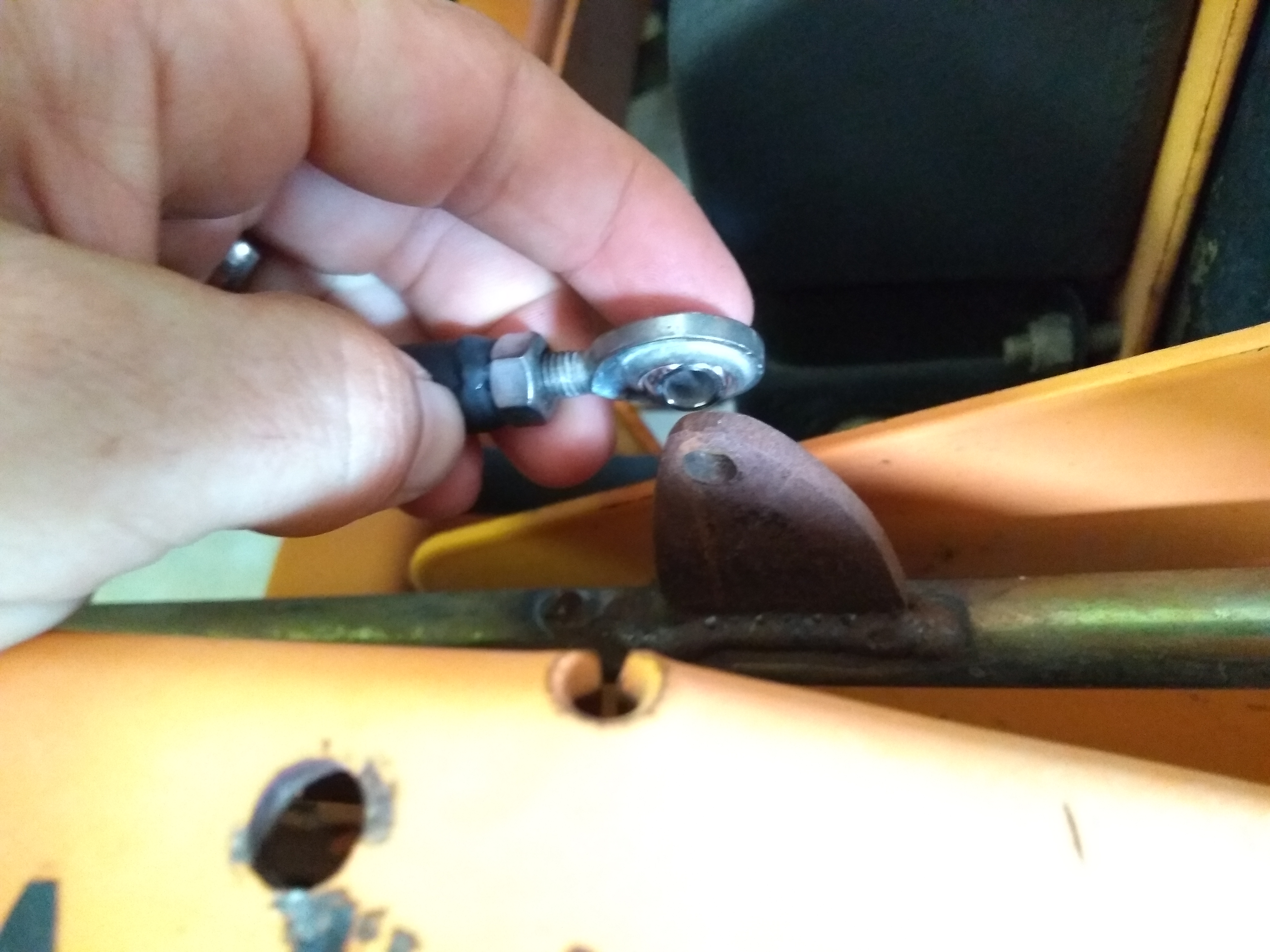
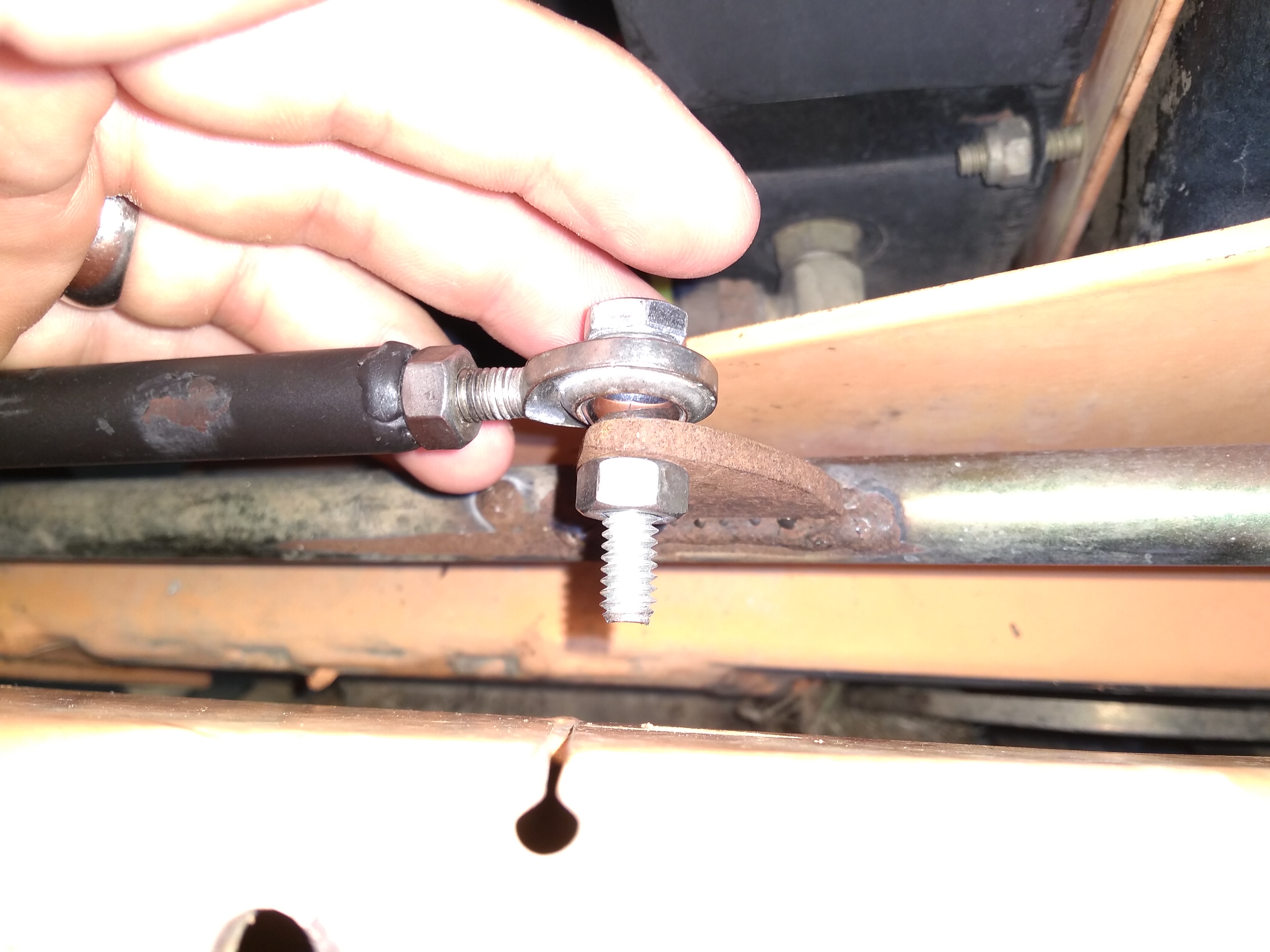
Connecting “Tab” Considerations
That rusty tab really is an eyesore, but it gets the job done. The hole in the top of the tab is ~1.50″ above the bottom of the tab. You can go ahead and cut a couple of ~1.5″x2″ triangles (or fancy tear-shaped lobes) out of the ⅜ steel bar, but I’d recommend holding off on welding the tab to the control arm until after we get the servo brackets and the linkage installed (otherwise you may guess wrong on the ideal location to weld the tab and not have all the adjustment available that will otherwise be duly afforded by the length of the threaded shaft on our rod ends). Once the rest of the linkage is in place, you’ll just move the servo to ~1500PWM (remember that 1500 PWM is the approximate middle of rotation for the Wingxine servo) and then thread the rod ends about half way into either end of the linkage, and then bolt one rod end to the servo plate and bolt the other rod end to the (not-yet-welded) tab. If you have that picture in your mind (i.e. picture the whole linkage installed on the mower, the wingxine servo plate at BDC, the rod ends half-way screwed into the adjustable shaft, but the business-end of the servo linkage with the connected tab isn’t yet welded to the control arm) — at that point you’ll just mark wherever the tab sits on the mower control arm and you’ll know exactly where to weld the tab.
If I haven’t succeeded in conveying the parts / methods needed to pull off this design, just ping me down in the comments and I think we’ll be able to get you in a good spot.
Mounting the Linkage Onto the Mower
Bolting the Wingxine Servos to the Servo Brackets
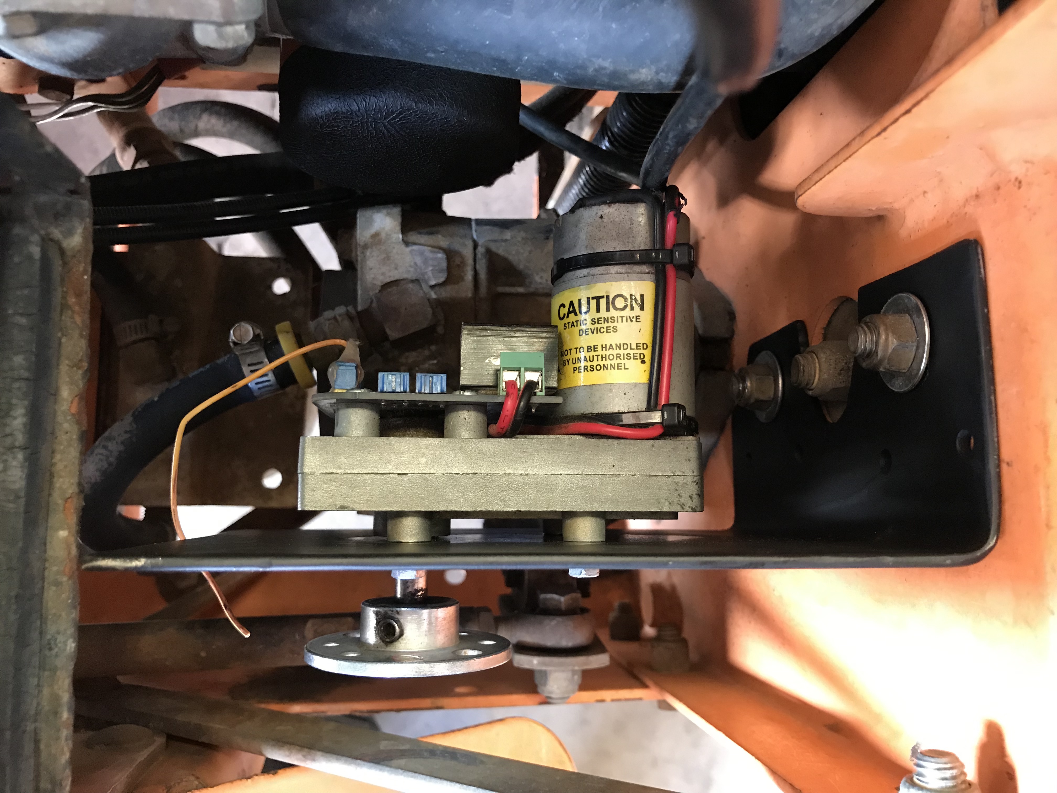
Now it’s time to bolt the Wingxine servos to our custom servo brackets. You’ll need to drill out 4 holes roughly in the center bracket in a rectangular pattern matching the 4 holes on the back of the wingxine servo. I’d suggest using a washer or 2 and some Loctite for each of these M4-0.7mm bolts so that you’re not tempted to over-tighten the bolt and strip out the thread.

Mounting the Servo Brackets to the Mower Frame
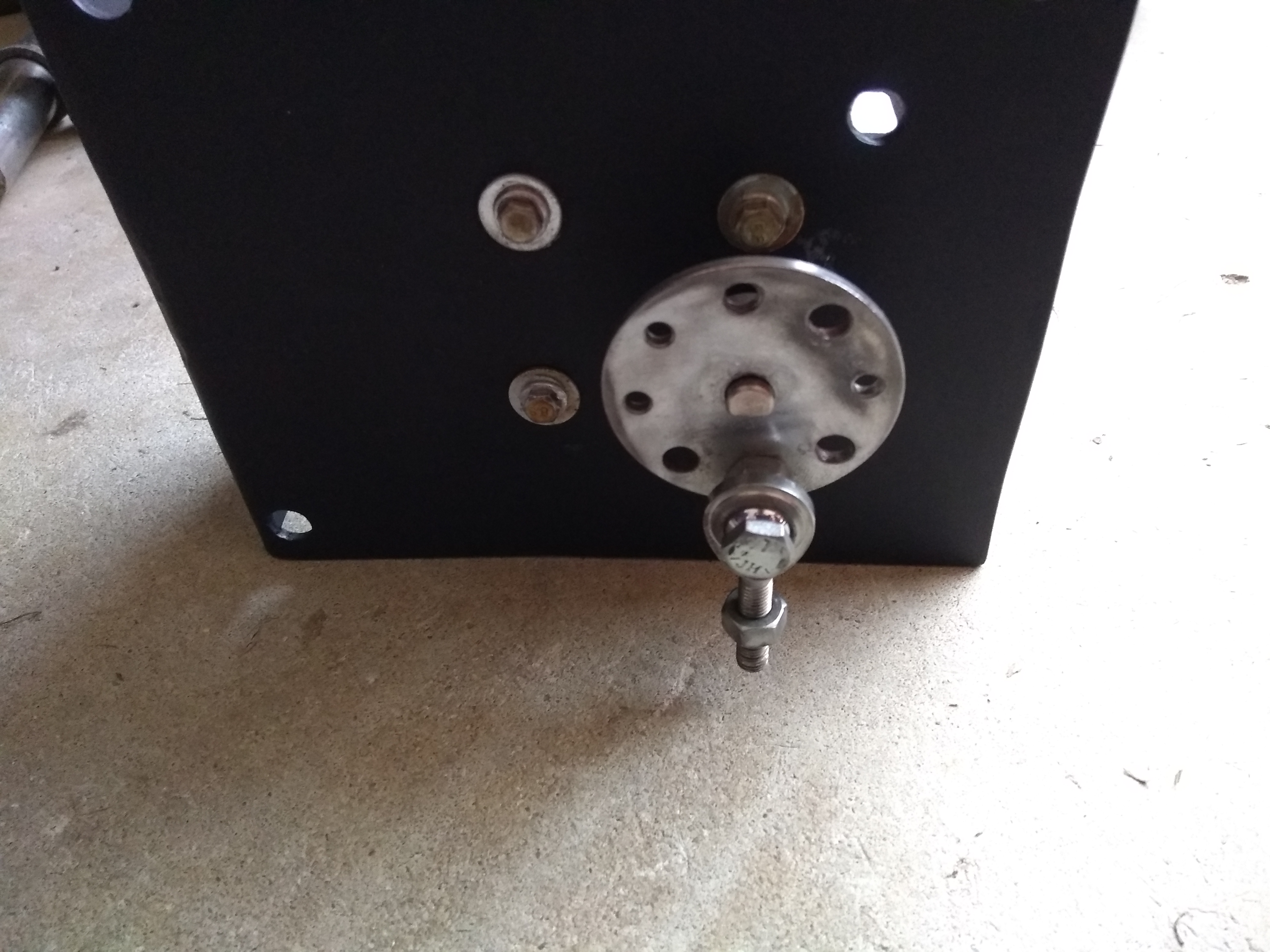
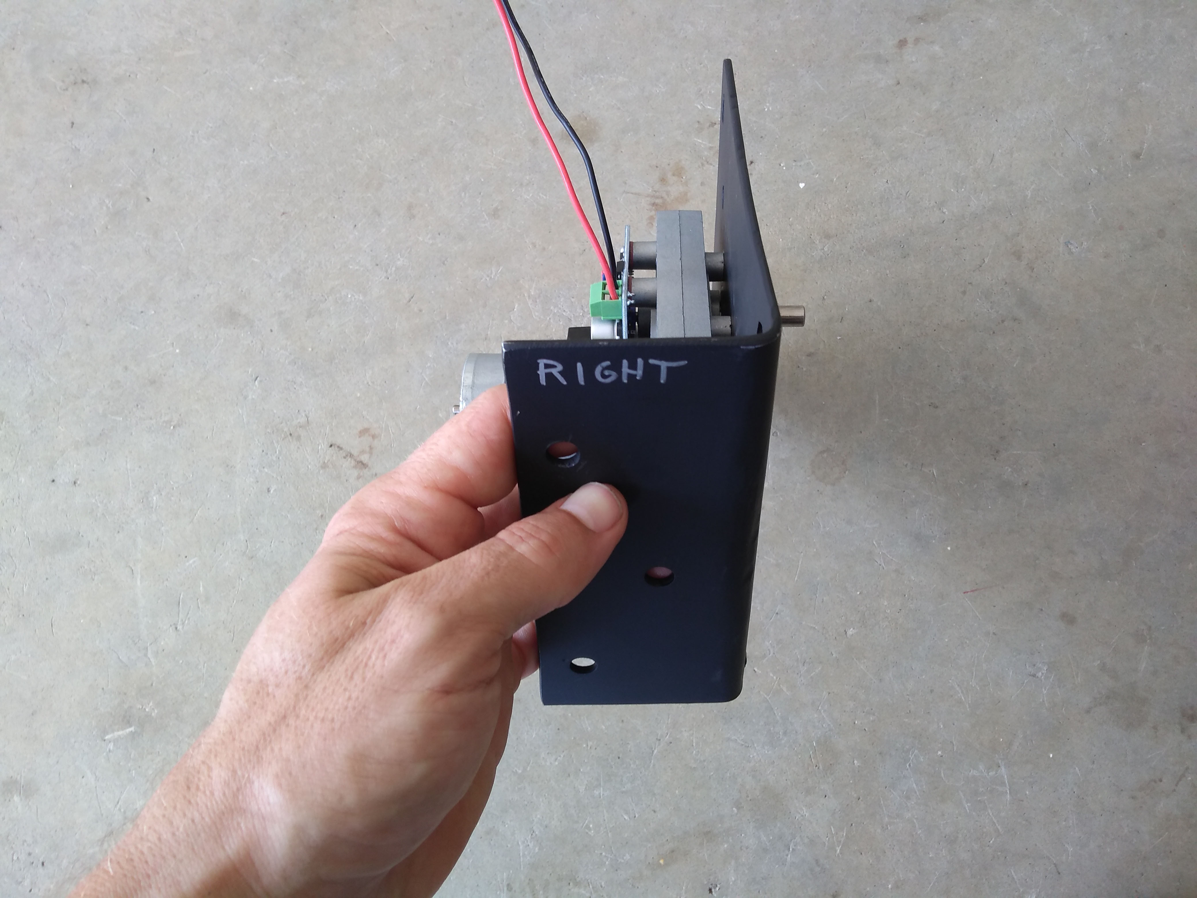
For the right-hand bracket, we were free from obstructions. After determining a location where the rod end that’s bolted to the servo plate will be flush above the mower control arm, we drilled 3 holes in the bracket and 3 holes in the mower and bolted the bracket to the mower.
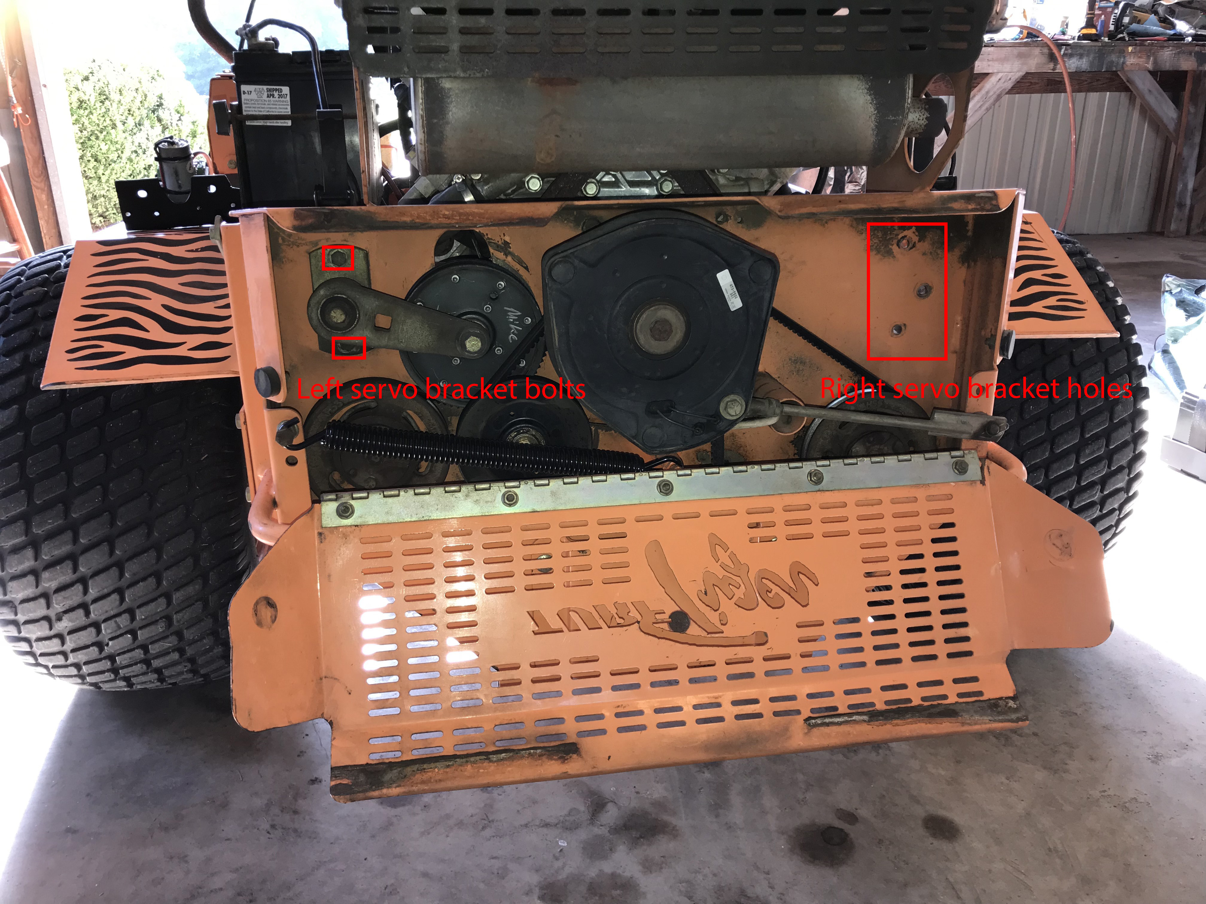

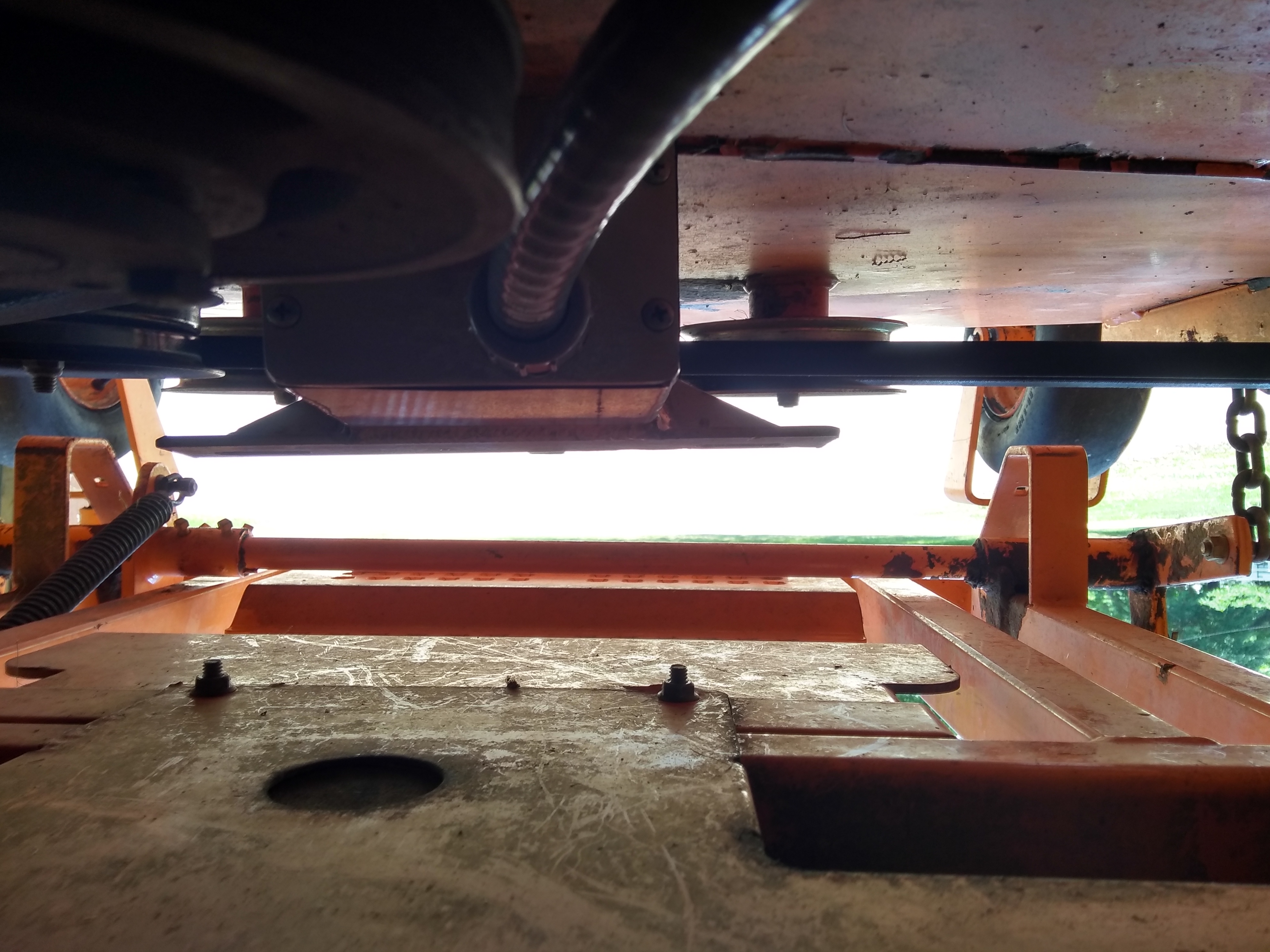
On the left side two mounting bolts for a tensioner pulley were exactly where we needed to be, so we just drilled 2 holes into the bracket to line up with the pulley’s mounting bolts and dropped our bracket right in place. Note we had to cut out a lobe from the center of the bracket to clear the pulley’s center bolt.

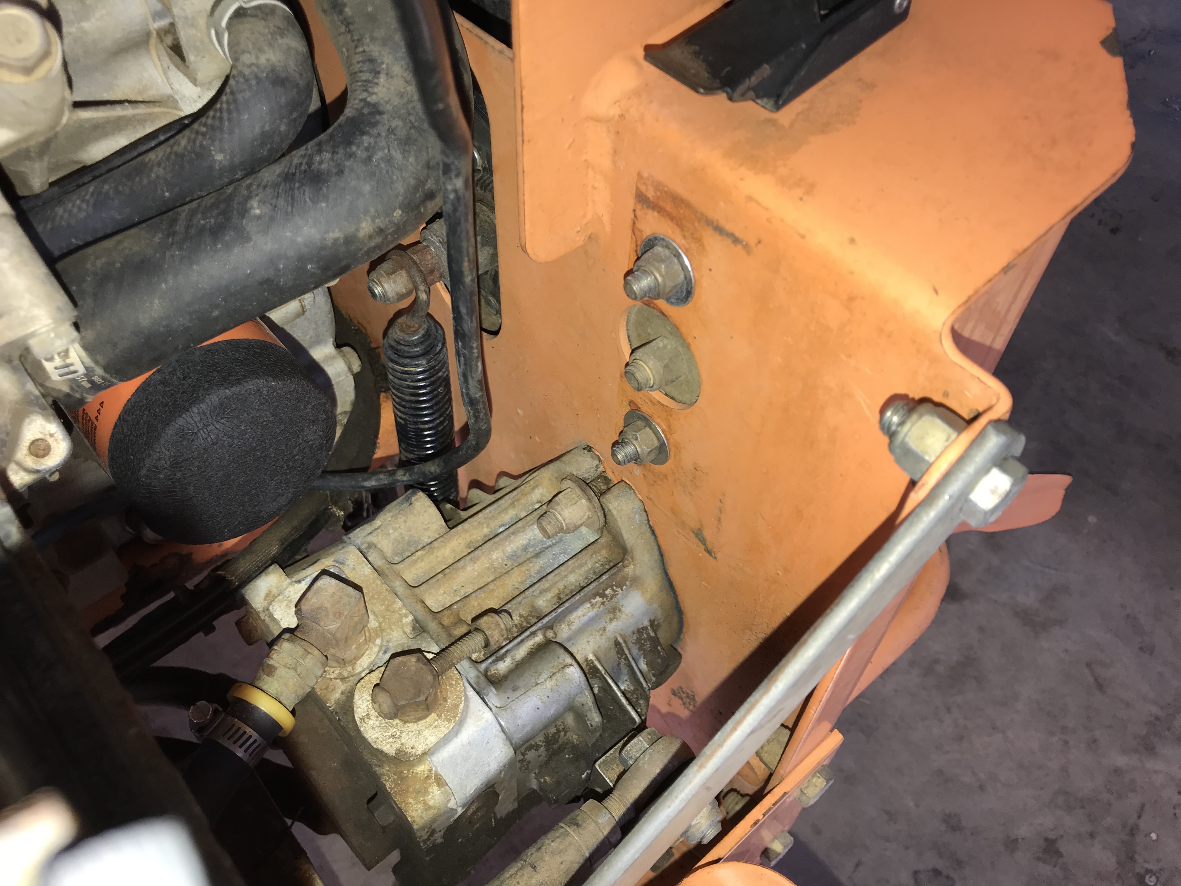


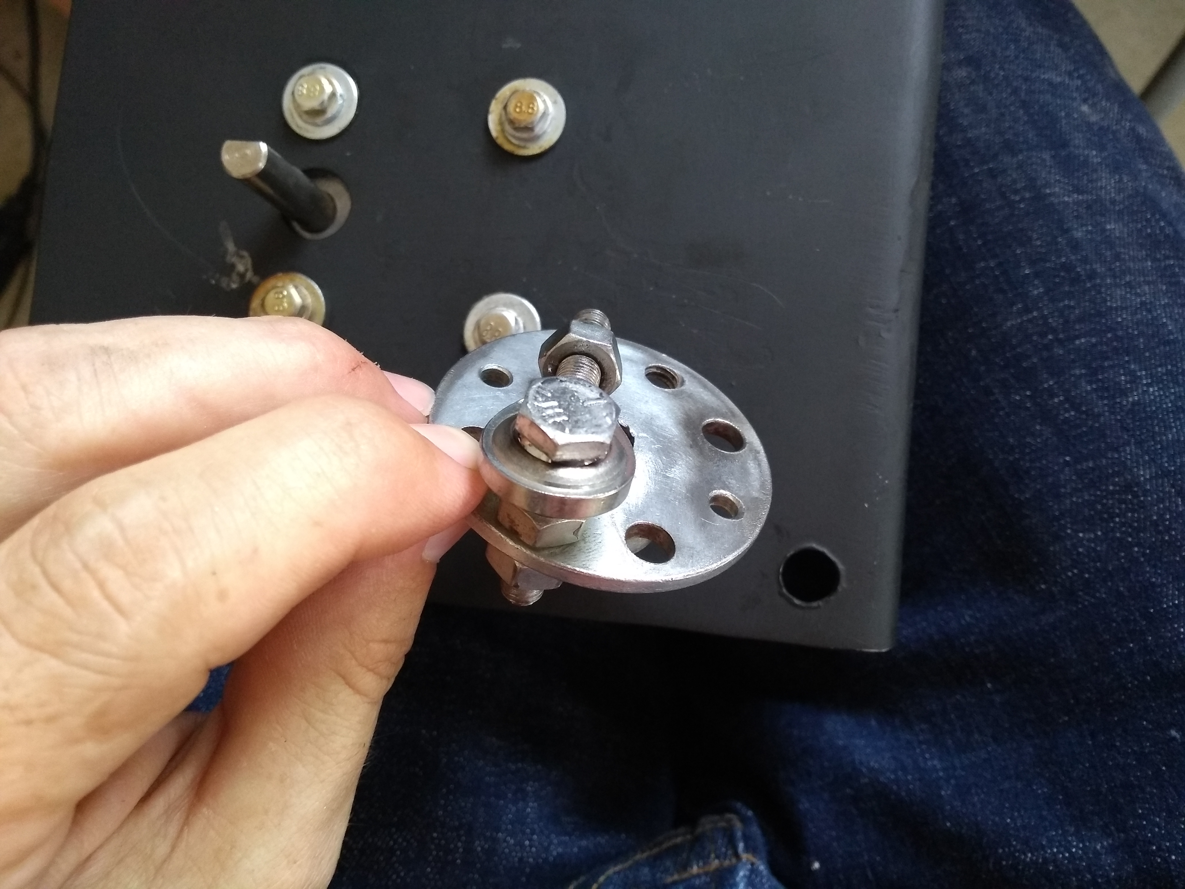
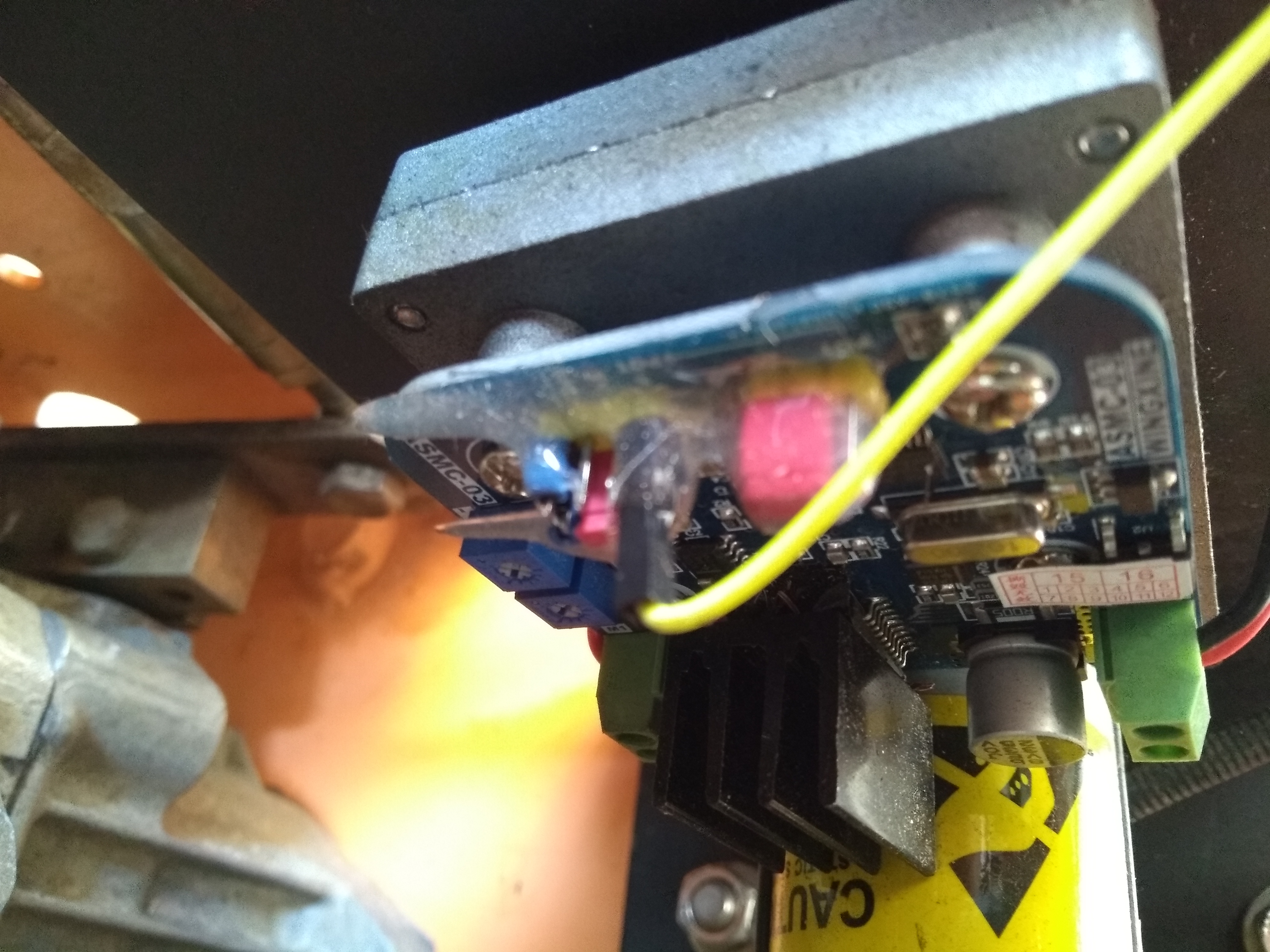
The exposed PCB on the servo enables quick adjustment (in particular the servo shaft’s range is controlled by a potentiometer — this is the inner-most blue plastic shroud visible atop the PCB in the picture directly above) but it’s clearly a temporary solution — it’s entirely reasonable to expect longevity out of these servos if we properly shield them from the elements. For now we’re going to leave that exercise to some future blog post if this discussion generates enough interest to warrant revisiting this setup.
Securing the Servo Plate to the Servo
Bolting the Male Rod End to the Servo Plate
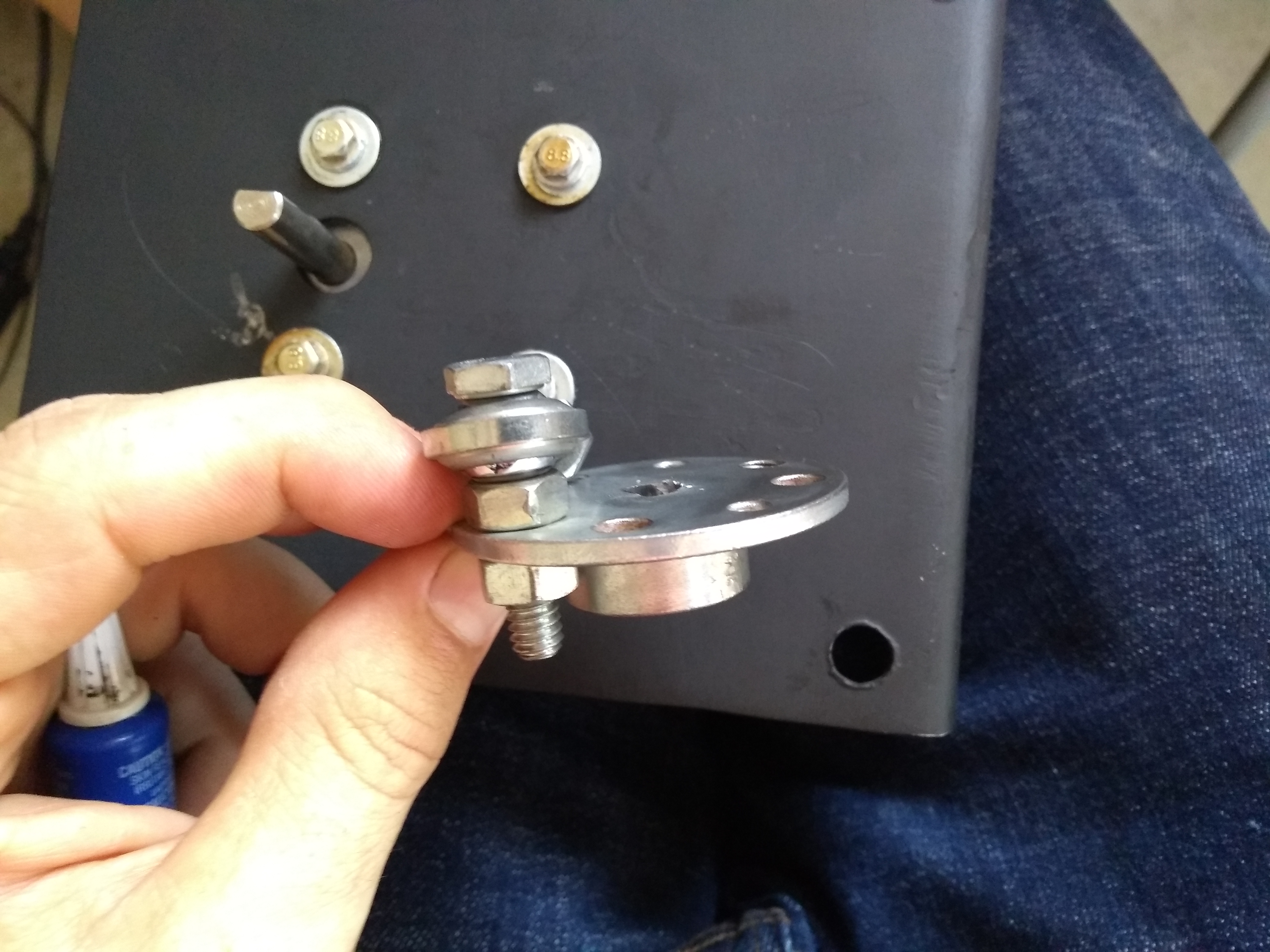
Now go ahead and thread the 12″ servo linkage we manufactured about half-way into the male rod end pictured above.

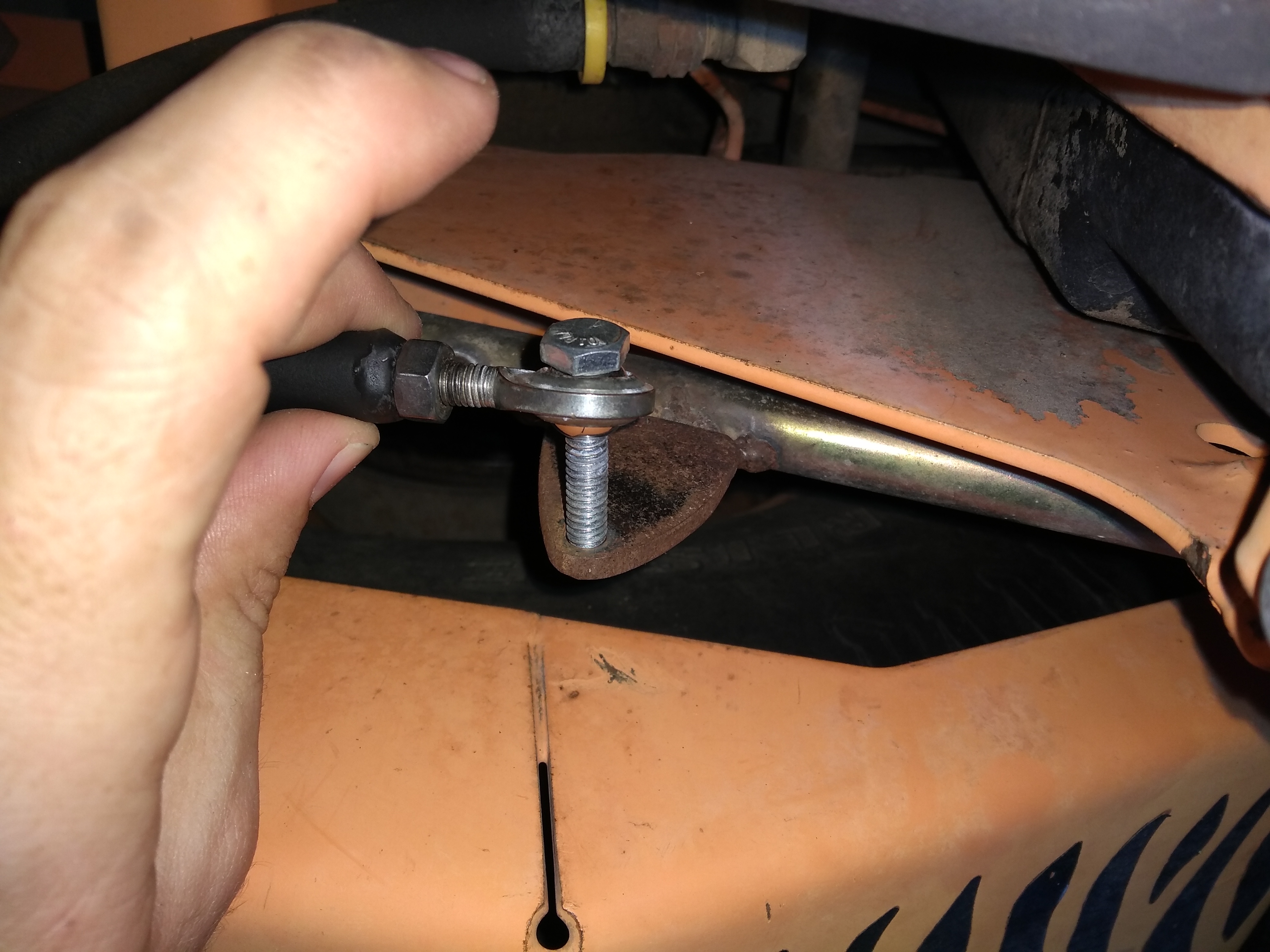
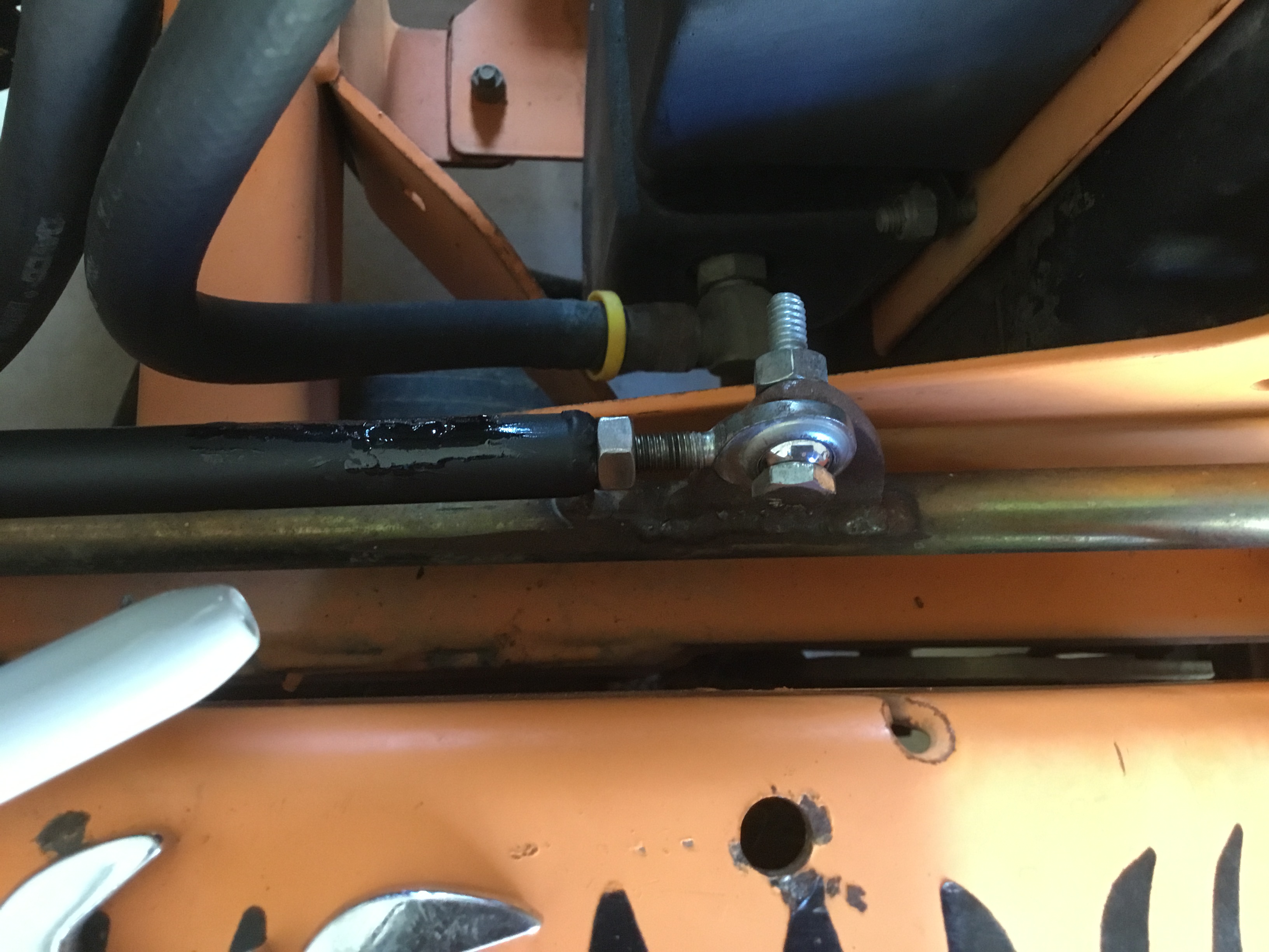
Welding the Tab to the Mower Control Arm and Bolting the Rod End to the Tab
Now that the servo bracket is mounted to the mower and the linkage is completely assembled (and the adjustable points on the linkage are around their mid-point), it’s time to bolt the connecting tab to the rod end at the other end of the adjustable linkage and mark the points on the mower’s control shaft where our tab is resting. Now go ahead and weld the tab to the control shaft and bolt the rod end to the tab, i.e.:

Adjusting the Servo Linkage so that Full Range of Motion Stays Safely Below the 3 O’Clock – 9 O’Clock Line of Disaster

All the warnings shouted from rooftops above about the 3 o’clock and 9 o’clock positions of the servo plate will hopefully now encourage you to move the servo arm throughout it’s range of motion and note the entire travel path of the servo plate. Assuming that your servo plate connection provides sufficient horizontal travel, you should be able to adjust the linkage to stay in the safe zone. To me it’s easiest to adjust the servo linkage at the welded tab end (only 1 nut to loosen to disconnect the rod end at that end). Remember that our rod ends are identically threaded, so you will have to unbolt the rod end from the welded tab (or unbolt the other rod end from the servo plate), loosen off the tightening nut securing the rod end against the servo linkage, and spin the rod end to increase or decrease the length of the servo linkage.
Once you’ve got the servo linkage adjusted to a length where moving the mower’s handle full forward and full reverse translate to a nice safe arc back at the servo plate connection, you may want to give yourself a good pat on the back — and then go ahead and give all the linkage nuts a quick check to ensure they’re all tightened.
Now we’re finished mechanically connecting both servo assemblies to the mower.
It’s time to give them juice.
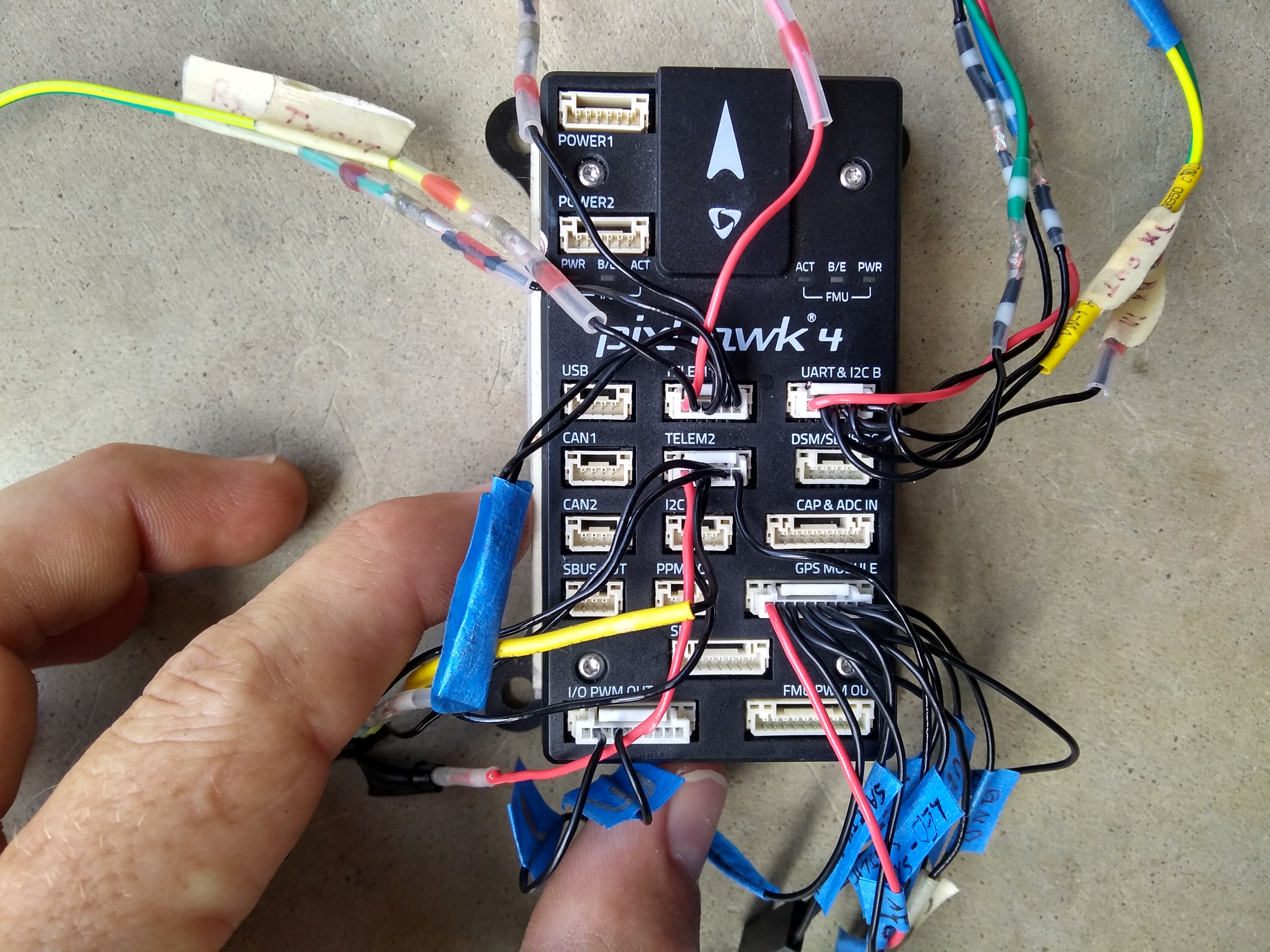
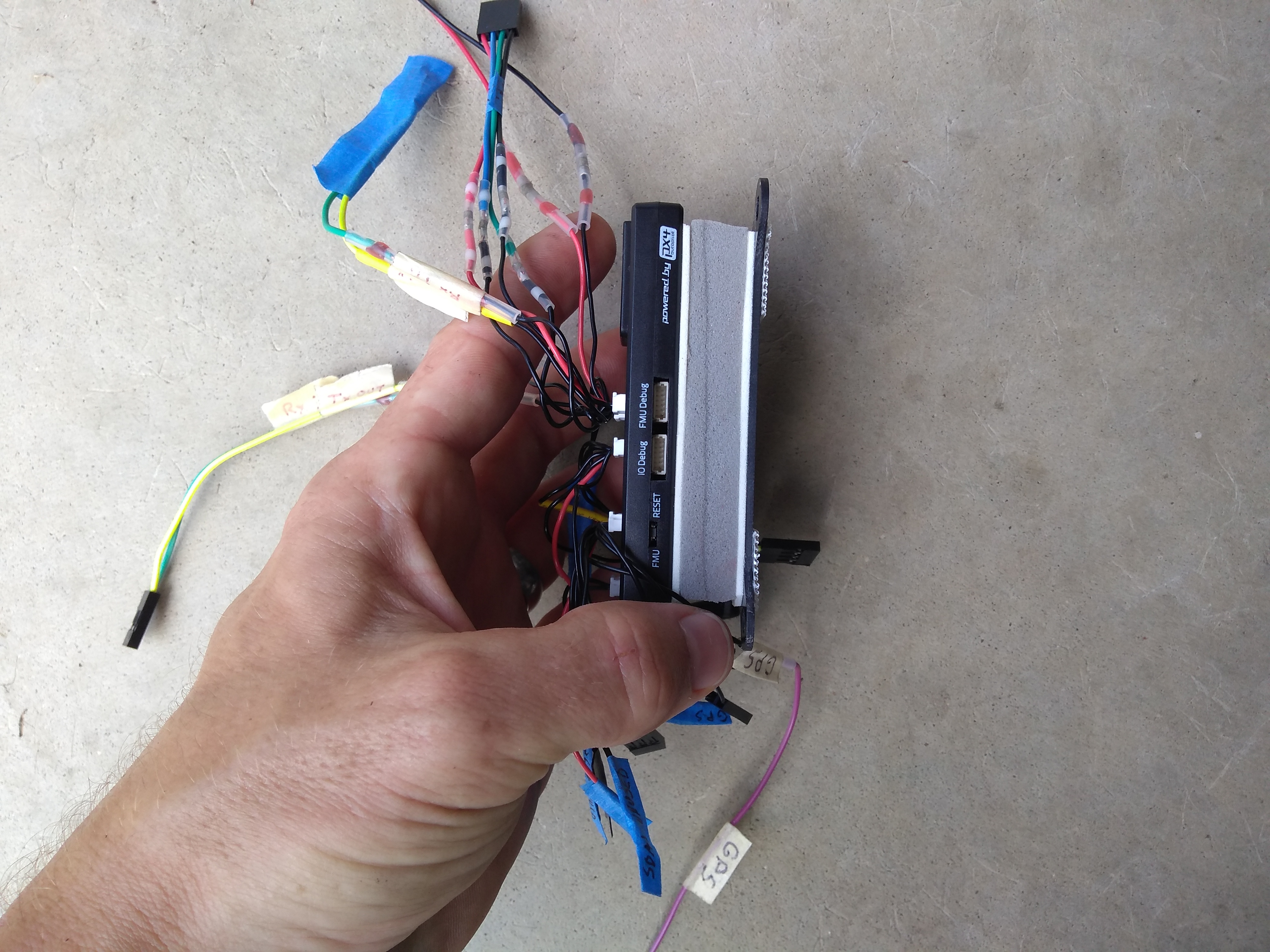
Wiring up the Servos
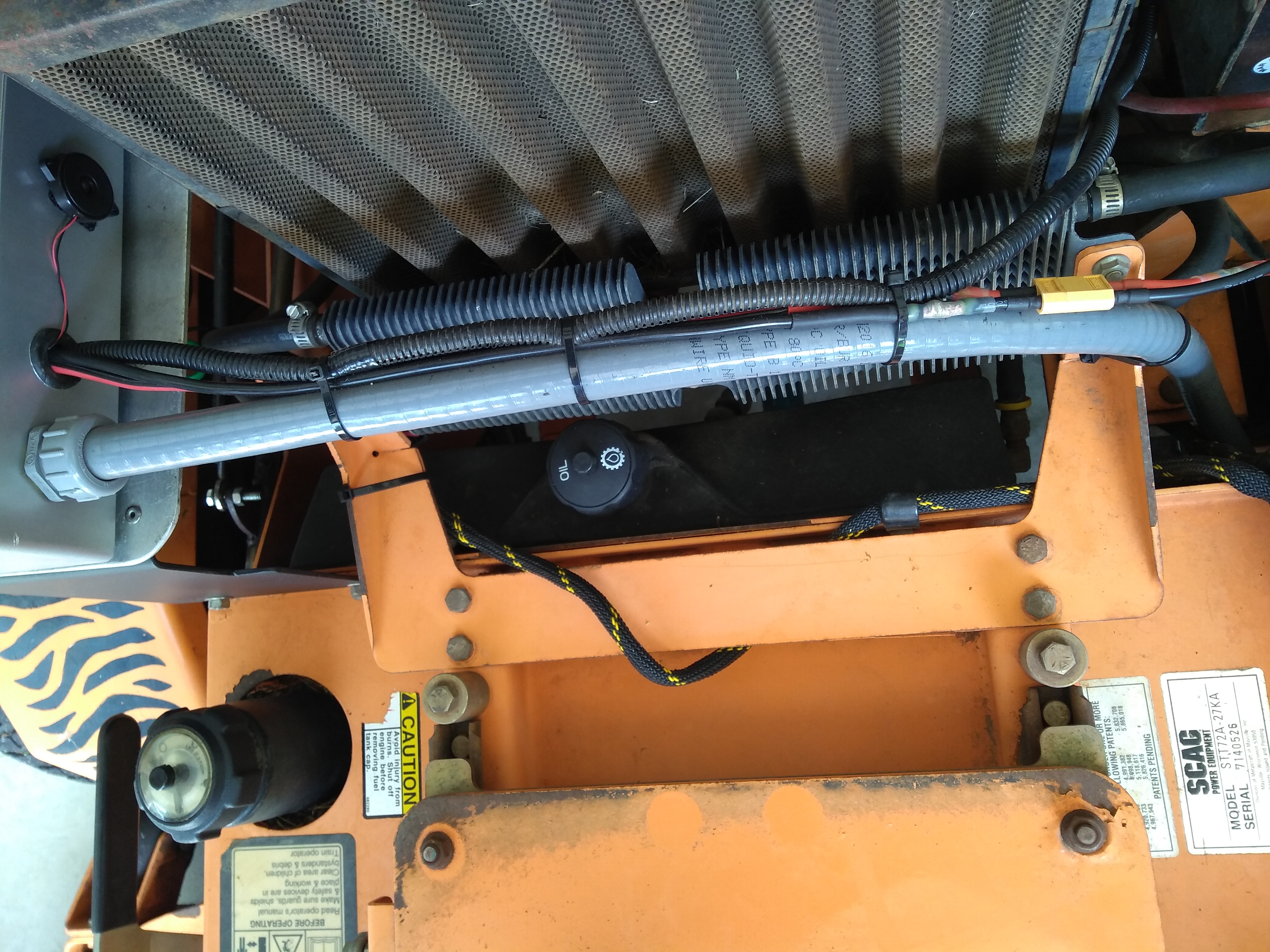
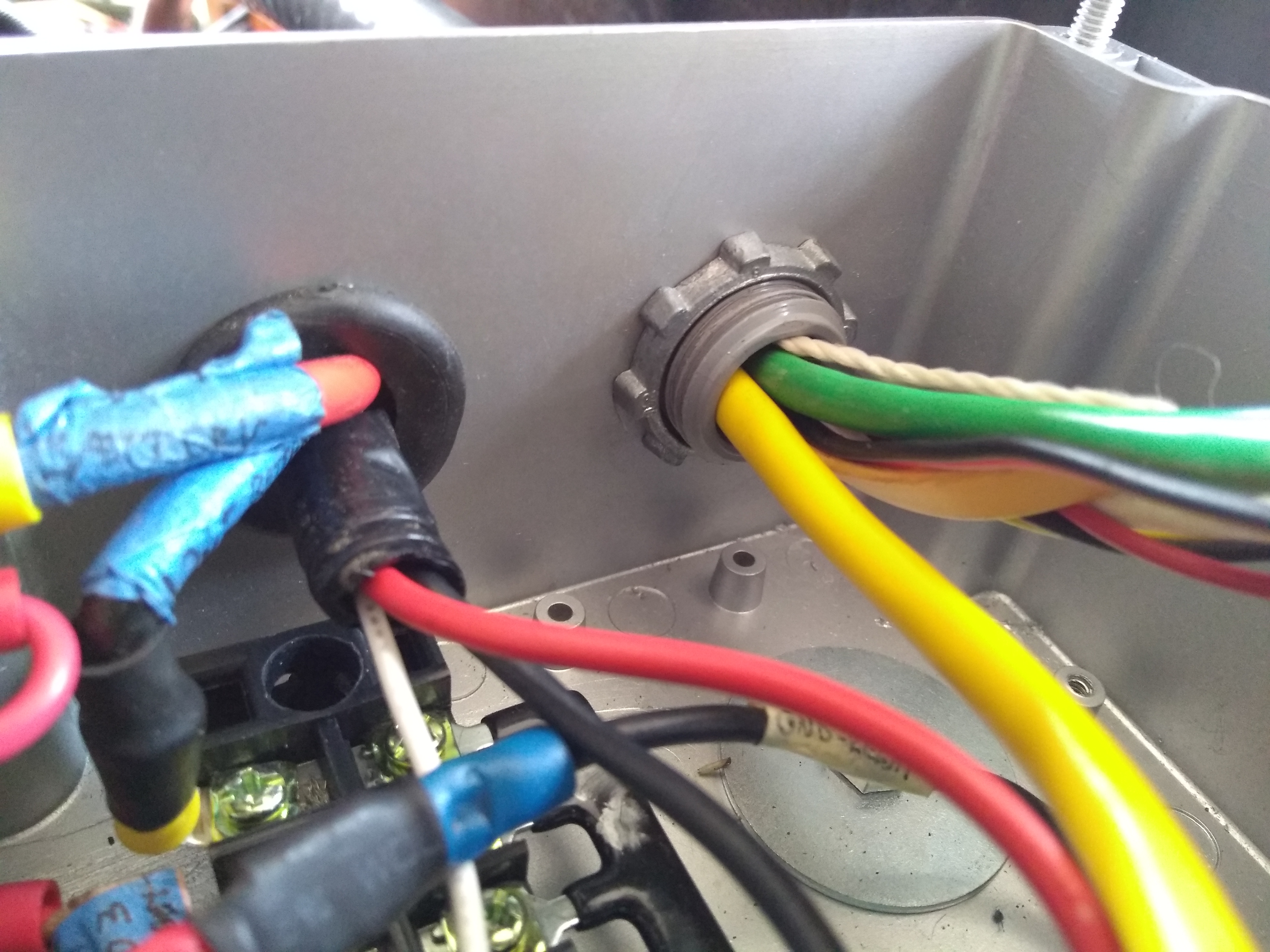
You’ll observe 3 wires running to either Wingxine servo — 12+, GND, and PWM signal from the Pixhawk.
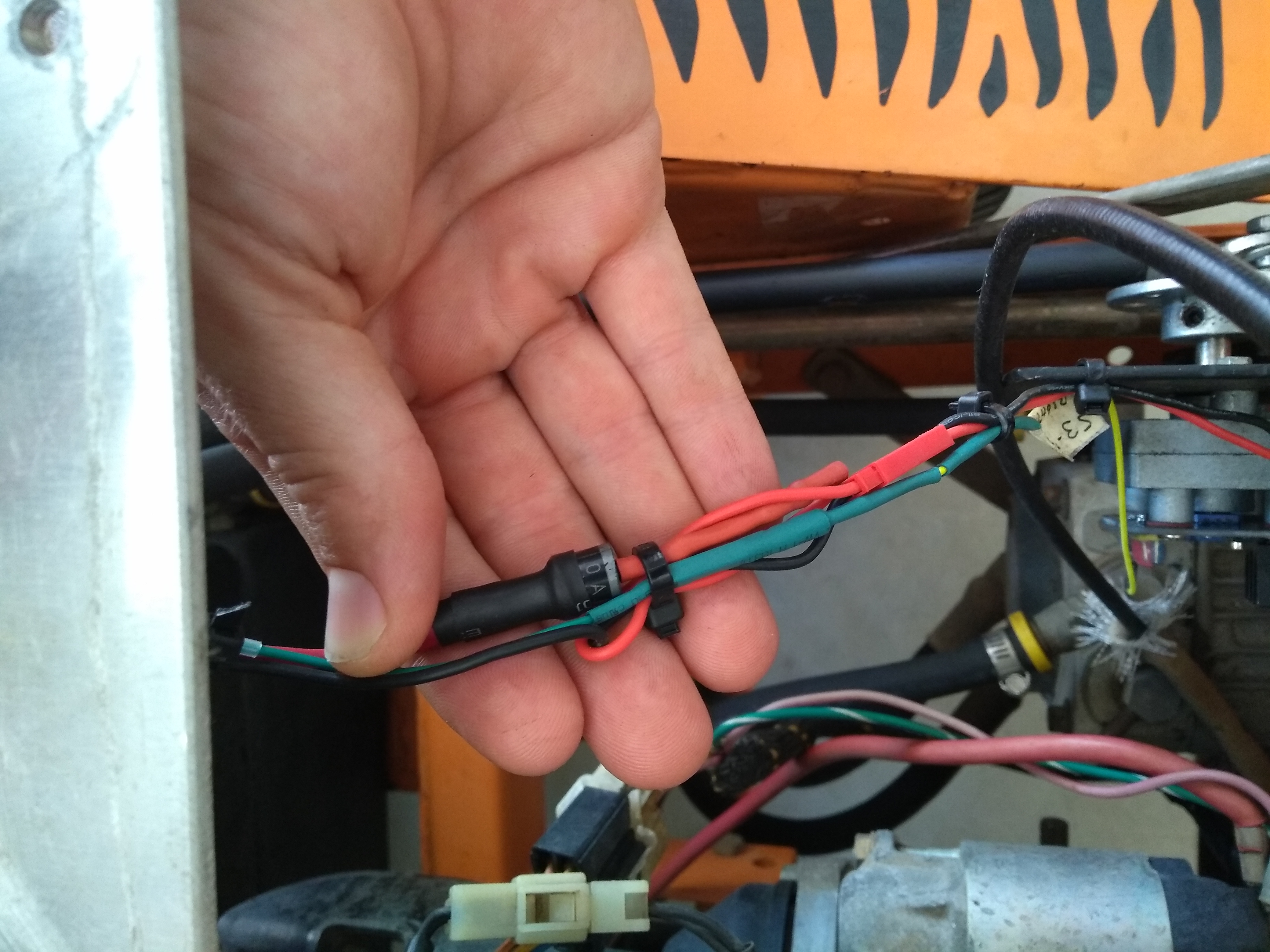
We’ll be able to trace the journey those PWM wires make from the servo up to the electronics box and then back down to the Pixhawk (mounted beneath the footrest on the Scag) a little later.
Configuring the Servos for ArduPilot in Mission Planner
This ArduPilot configuration dance is really just figuring out what PWM value makes each Wingxine servo go to neutral and then which PWM values tell the Wingxine servos to move to the maximum forward and then the maximum reverse position that you’re comfortable with. Restraint is obviously encouraged here — especially on early runs with a new build.
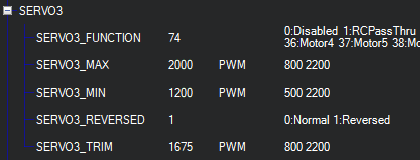
On skid-steer vehicles, ArduPilot controls the left wheel via the “Servo1” settings and the right wheel via the “Servo3” settings.

Once you’ve invested a little time moving both mower arms to full reverse, full forward and neutral with the joystick, you should be able to ballpark those 3 values for each arm on your robot. Just remember that the PWM values in Mission Planner you’re actually sending to the servos (and thus where you’ll find the values you’re going to enter in the SERVO1/SERVO3 settings) are ch1out and ch3out — it’s easy for your eyes to lose track and end up looking at the ch1in and ch3in numbers.
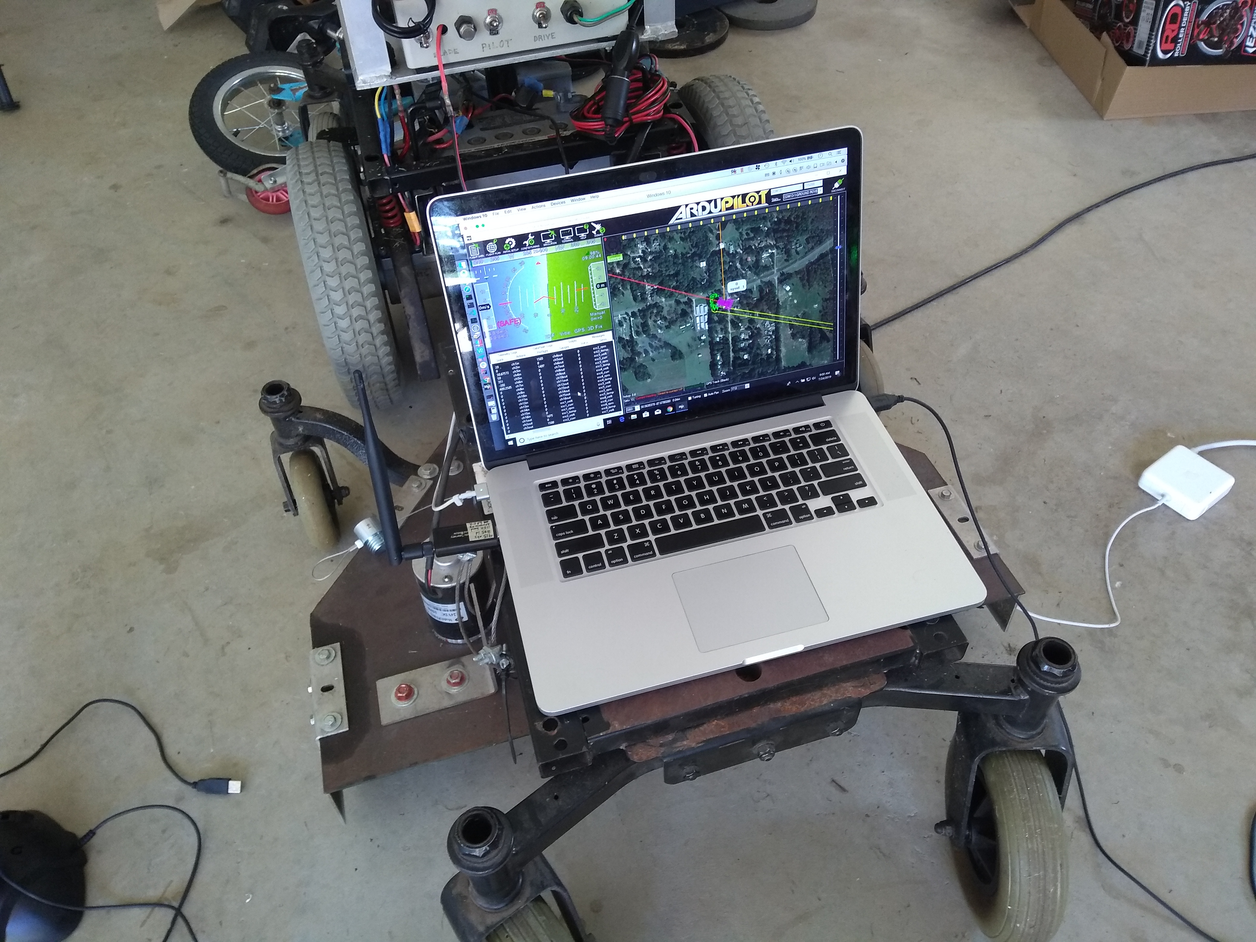
This servo setup has been a fair amount of effort, but eventually the setup will start to function similar to this:
Hopefully we’ve covered enough to at least paint a picture in your mind of the points involved in this setup.
If you’re following along with a similar setup but something isn’t quite clicking from the ArduPilot side, then maybe download your configuration params in Mission Planner and compare them with the params on our build.
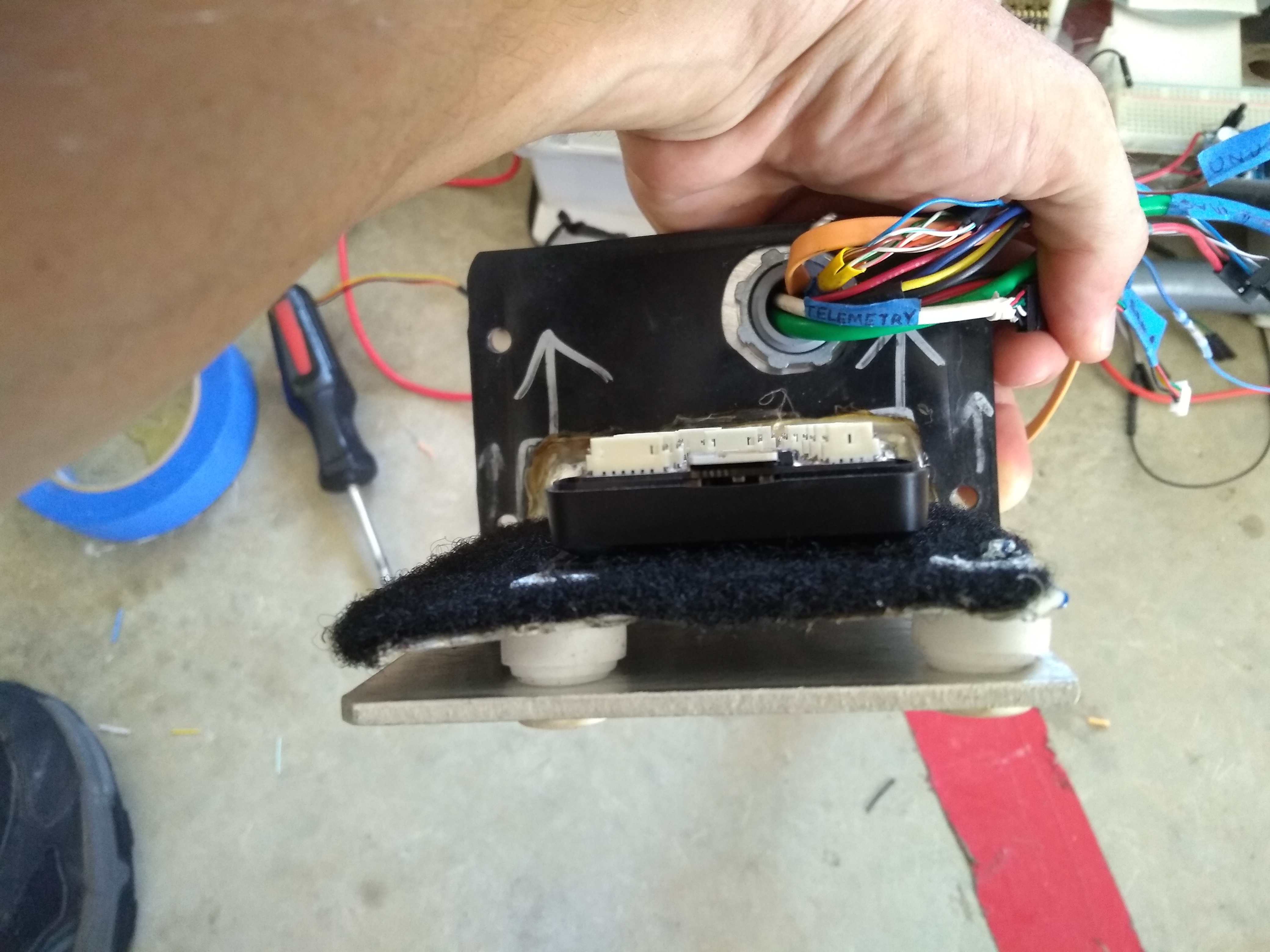
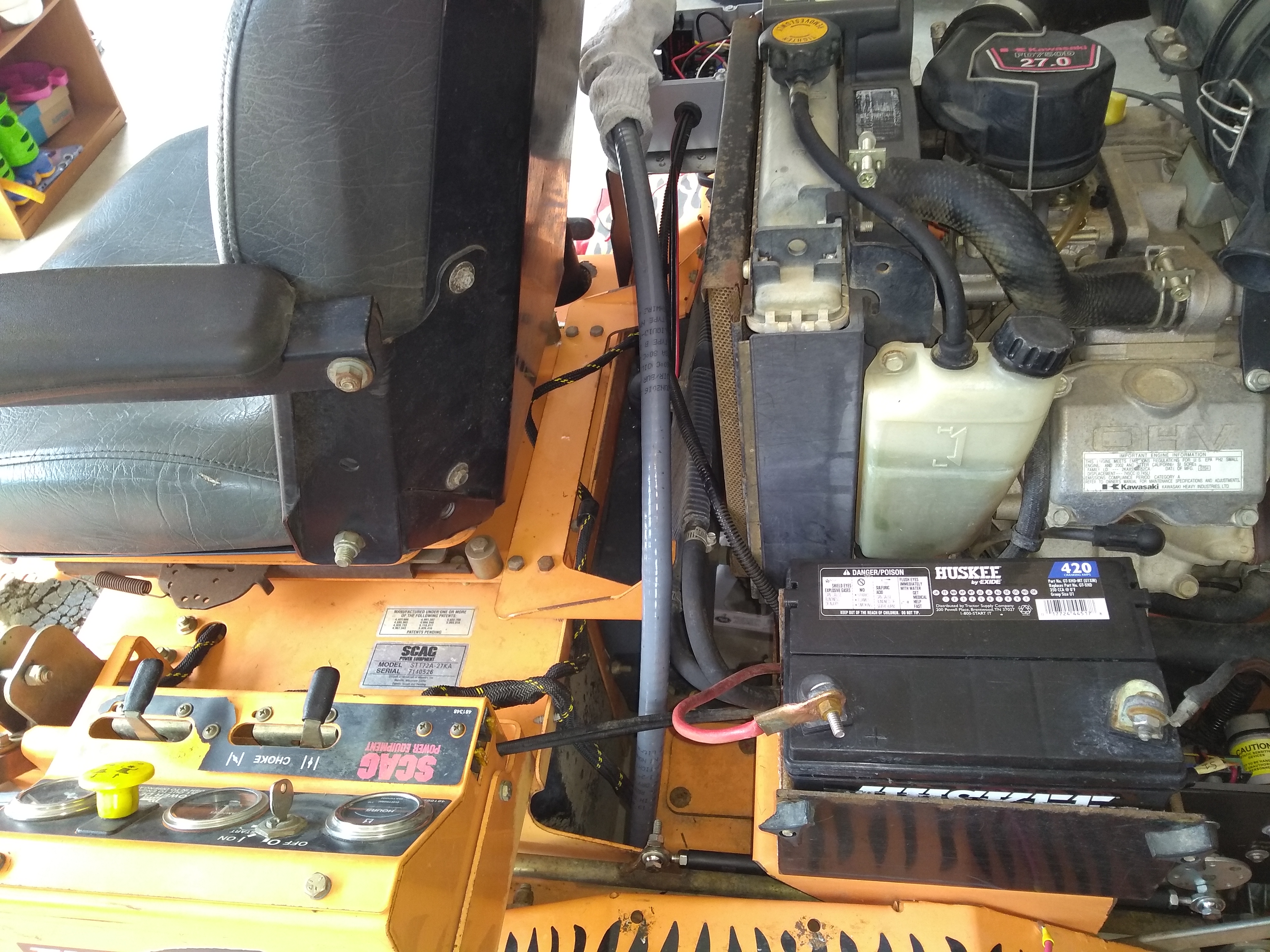
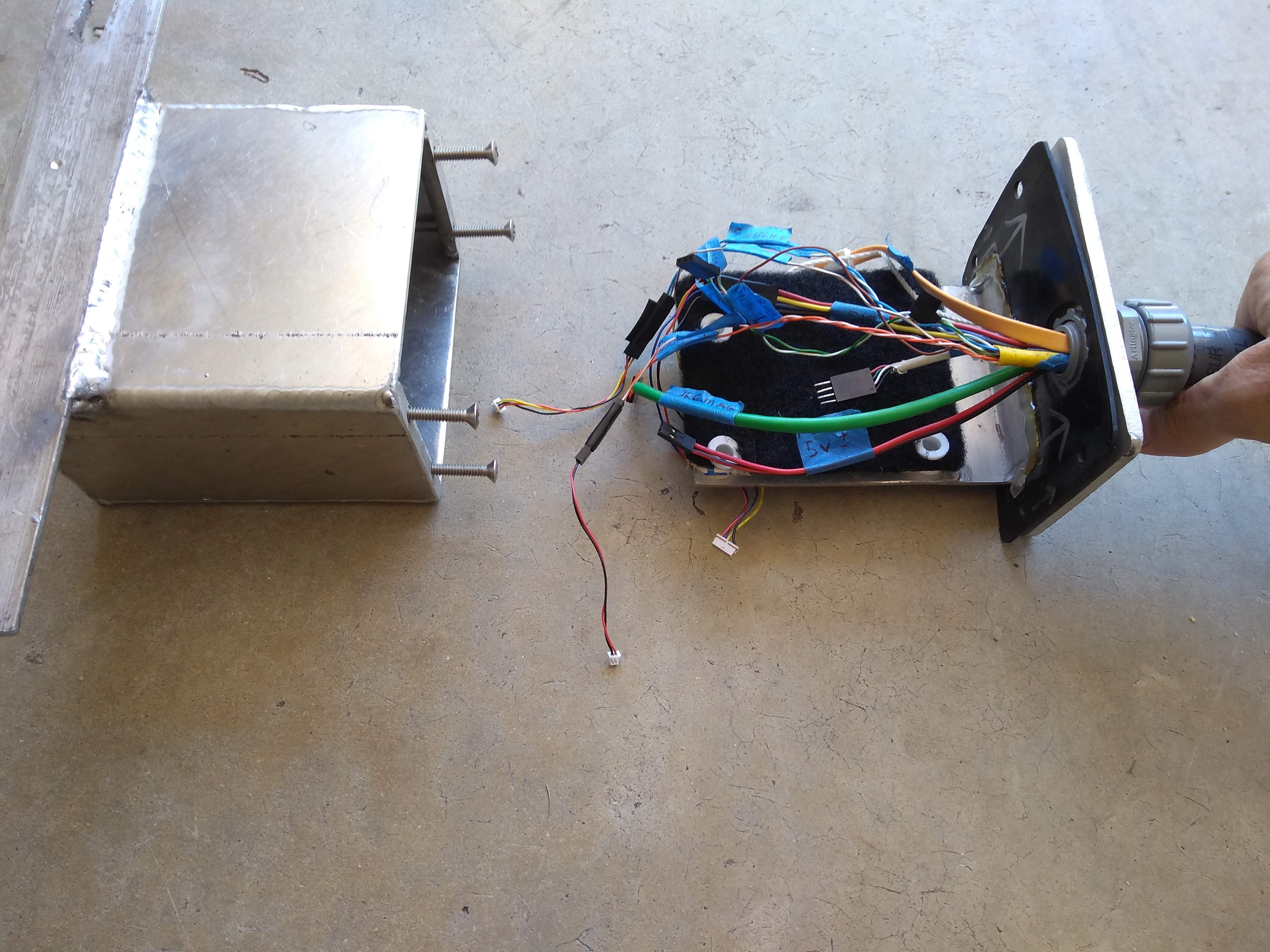
Electronics
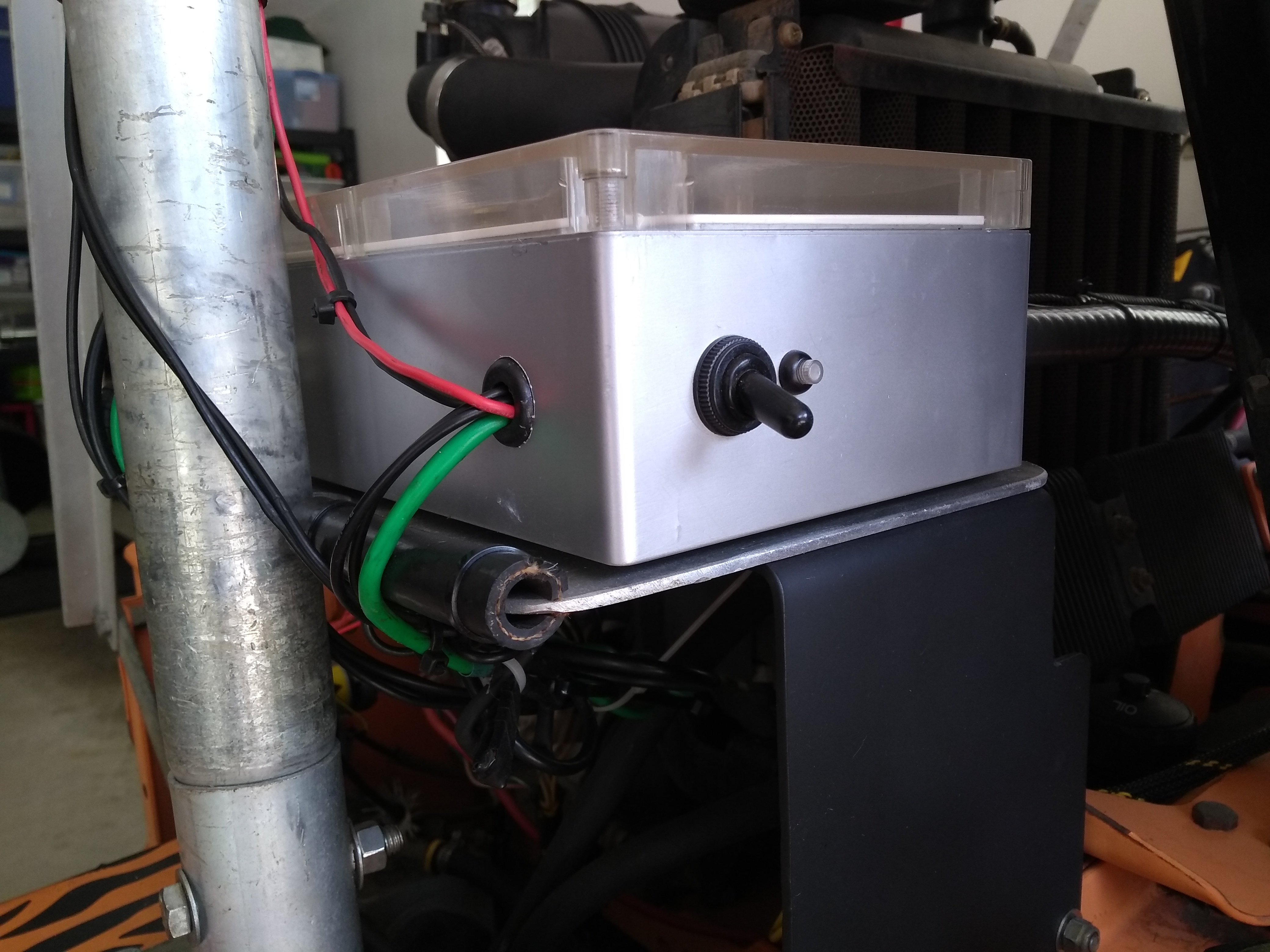
The main electronics box (pictured above) contains all the components that aren’t picky about their mounting location. The cast of characters here is largely the same as we’ve seen in previously discussed builds with the exception that the Pixhawk is not mounted in this box — it’s down below closer to the rover’s center of gravity (more on this in a bit). You’ve likely noticed that the wiring in the box could use some spring cleaning — somehow I’m pretty zealous about labelling but lazy about tidying up the wires too early.
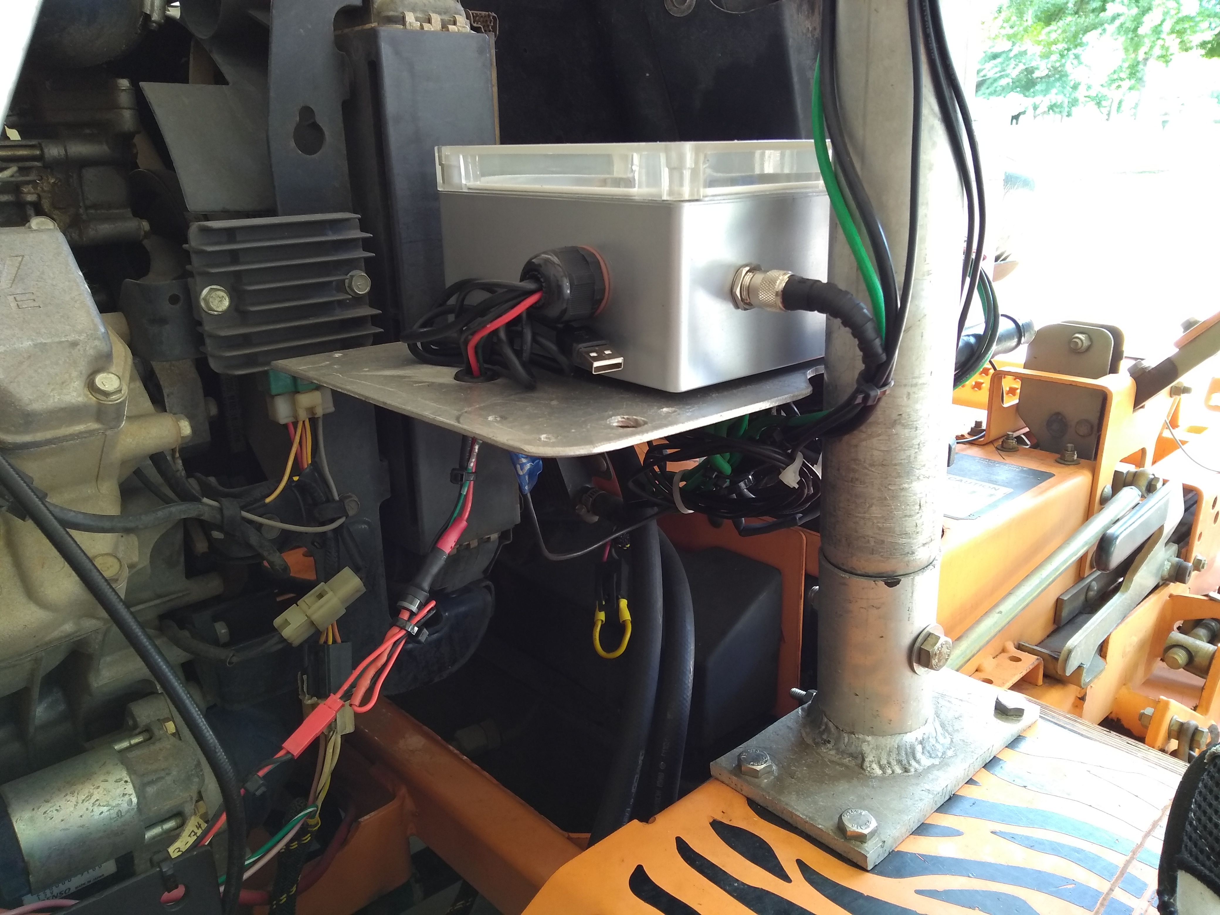
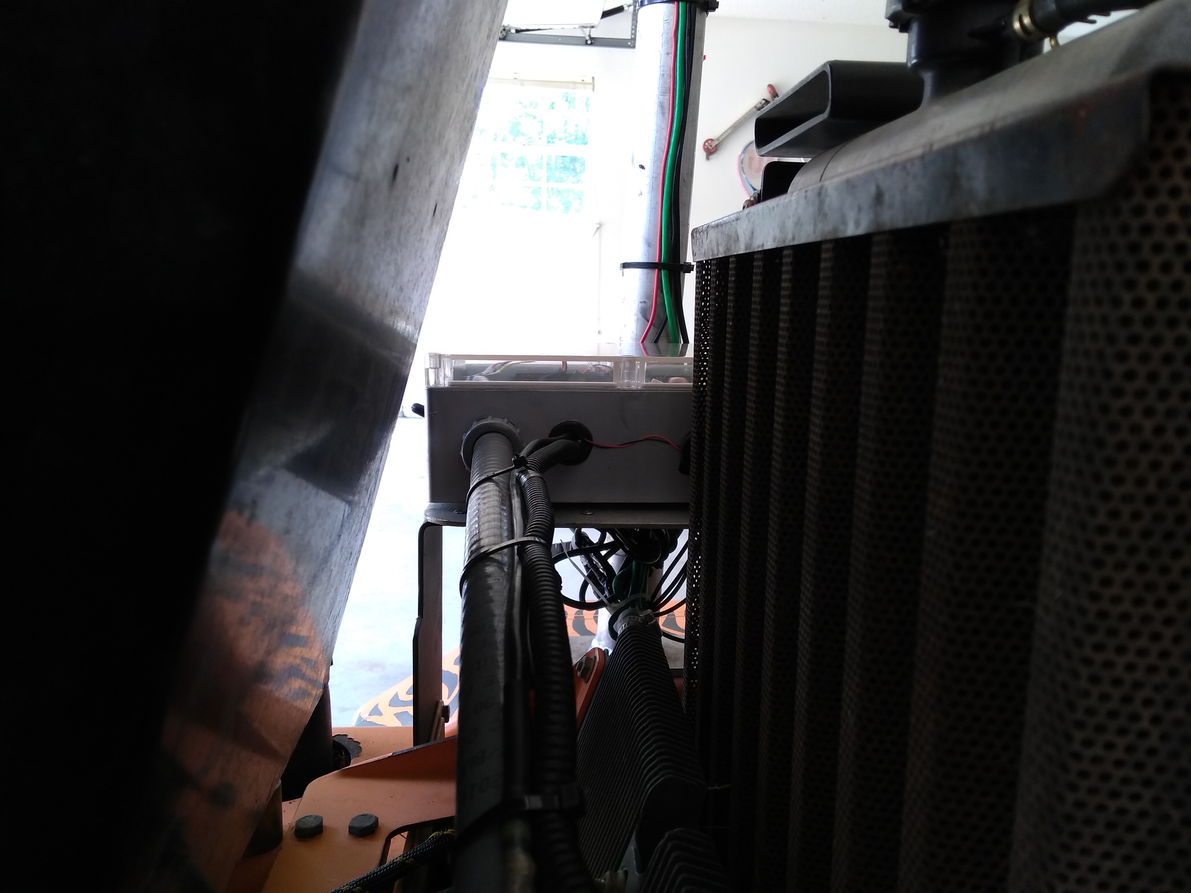
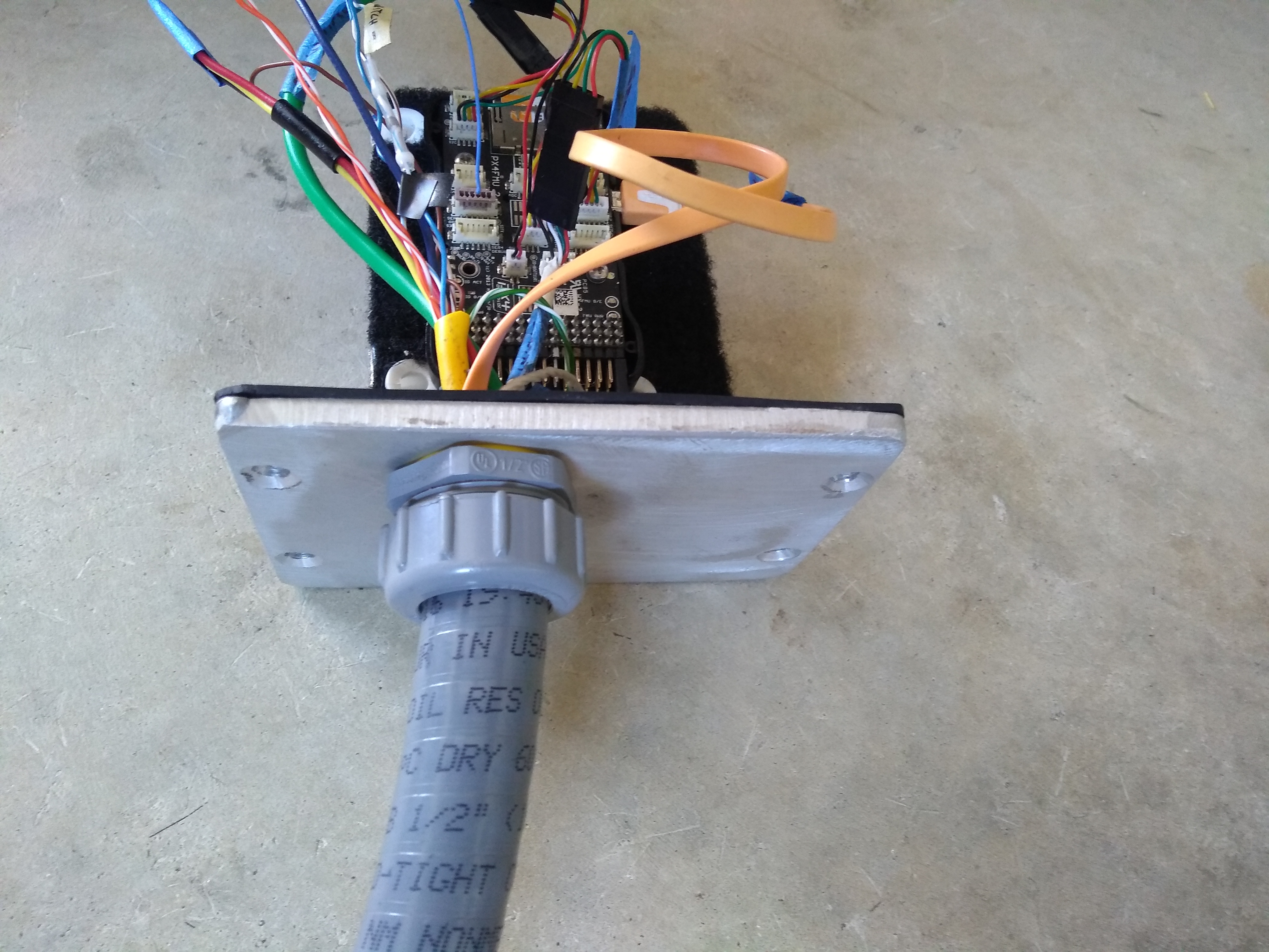
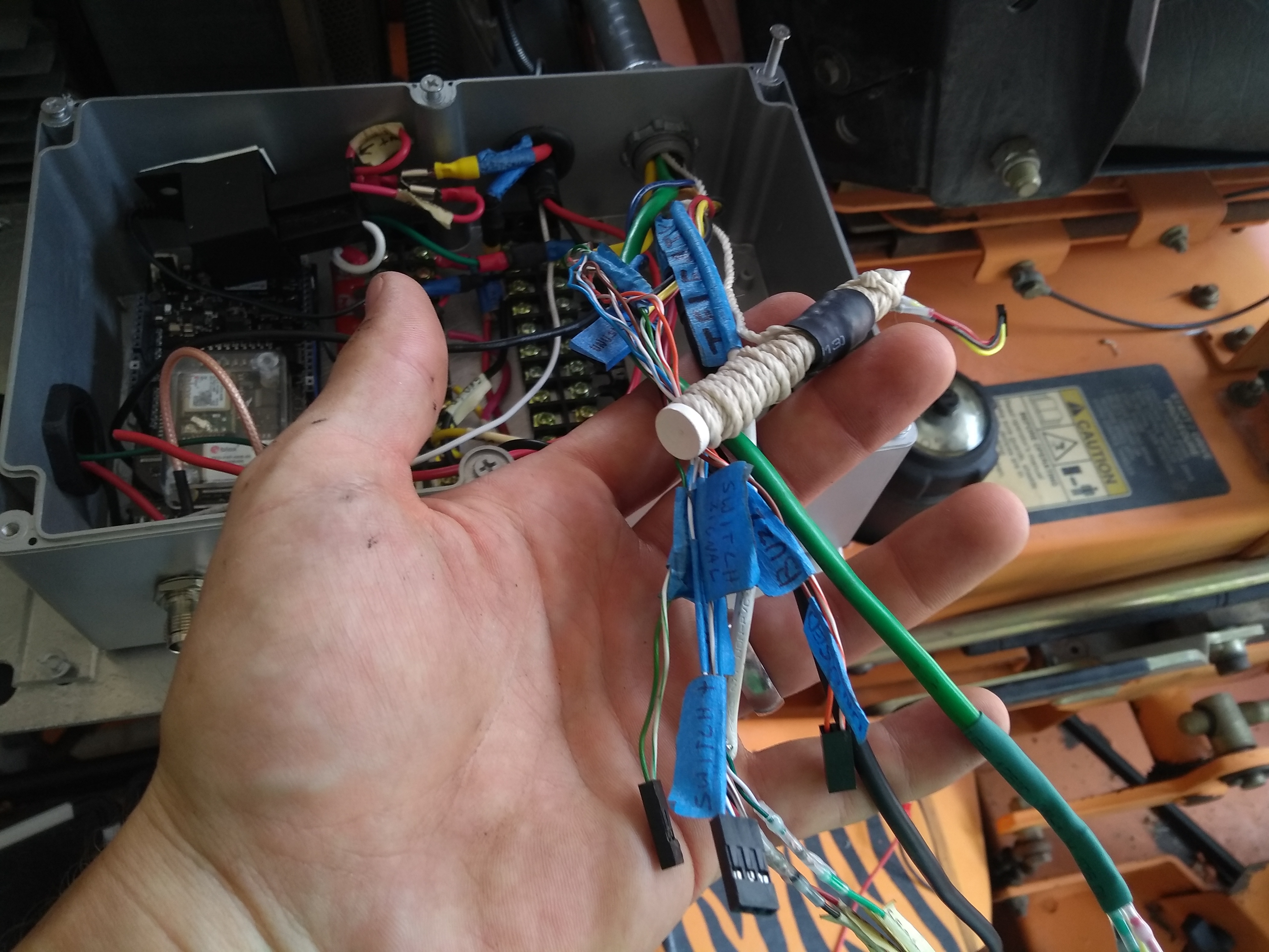
Additional Pictures for (Hopeful) Clarity
Let’s go ahead and drop a collection of pics taken at different angles to hopefully clarify pieces we may have overlooked.
Aluminum Roll Bar
The electronic components mounted atop the aluminum roll bar don’t want to break up, but they do need some space.
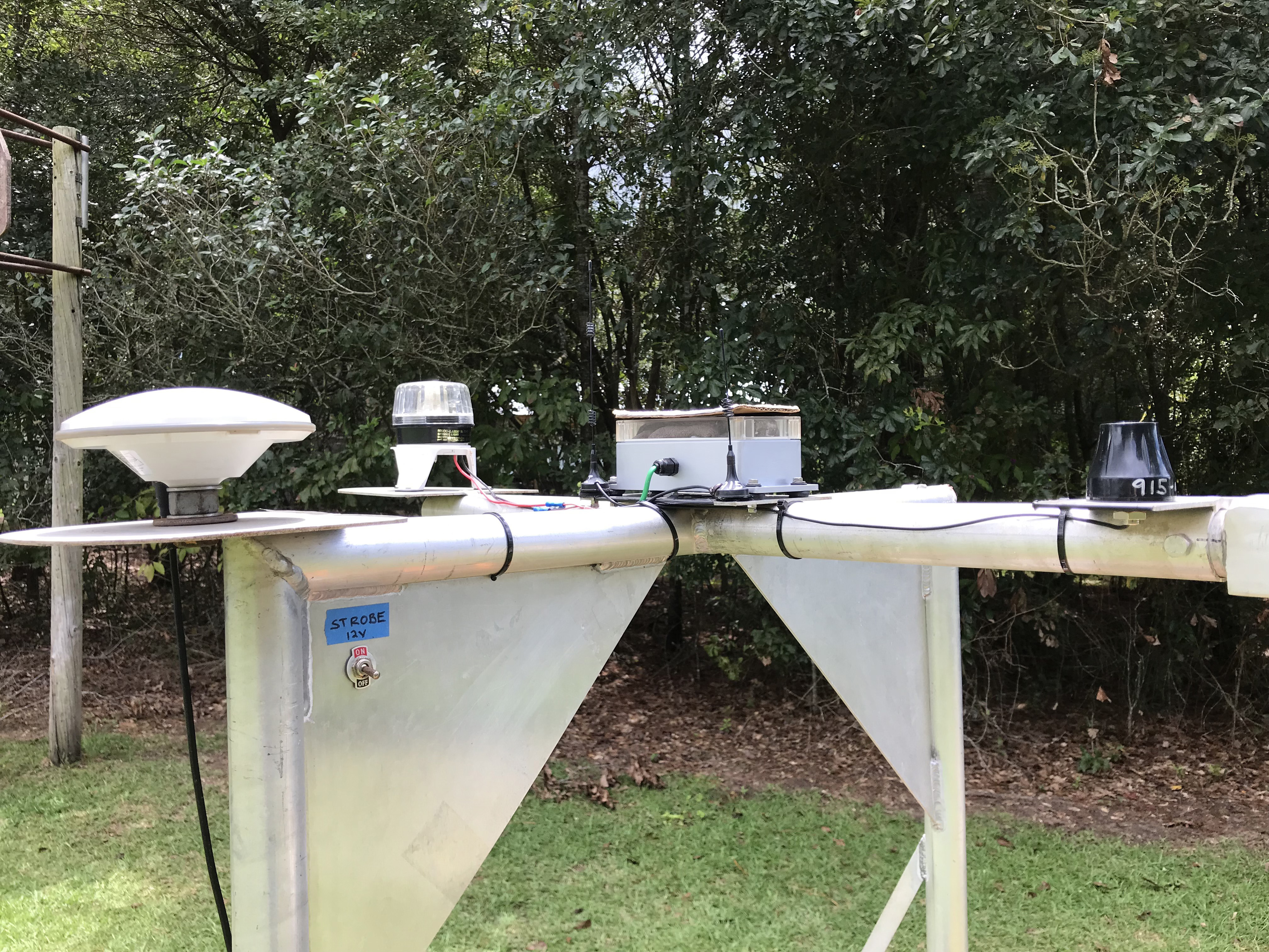
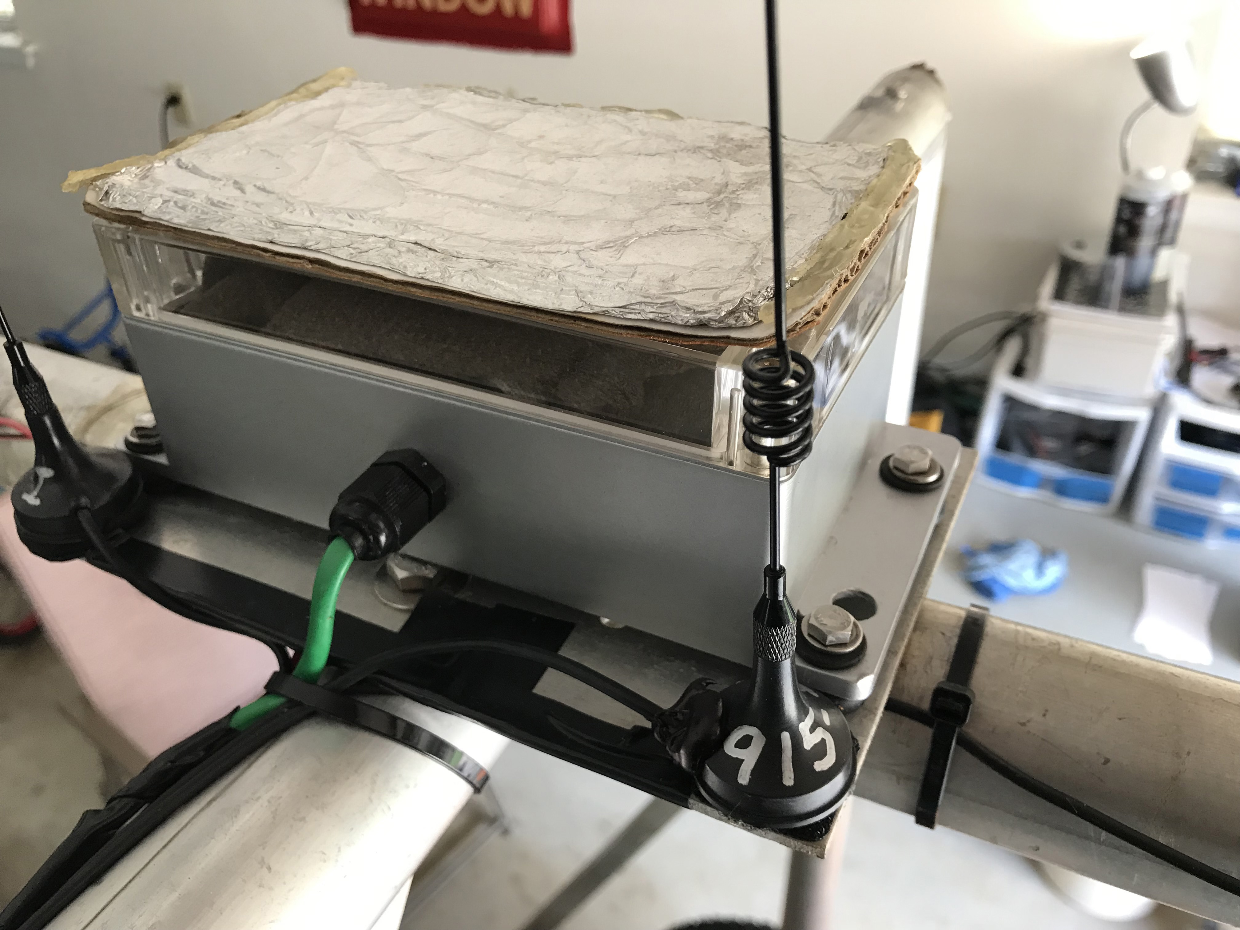
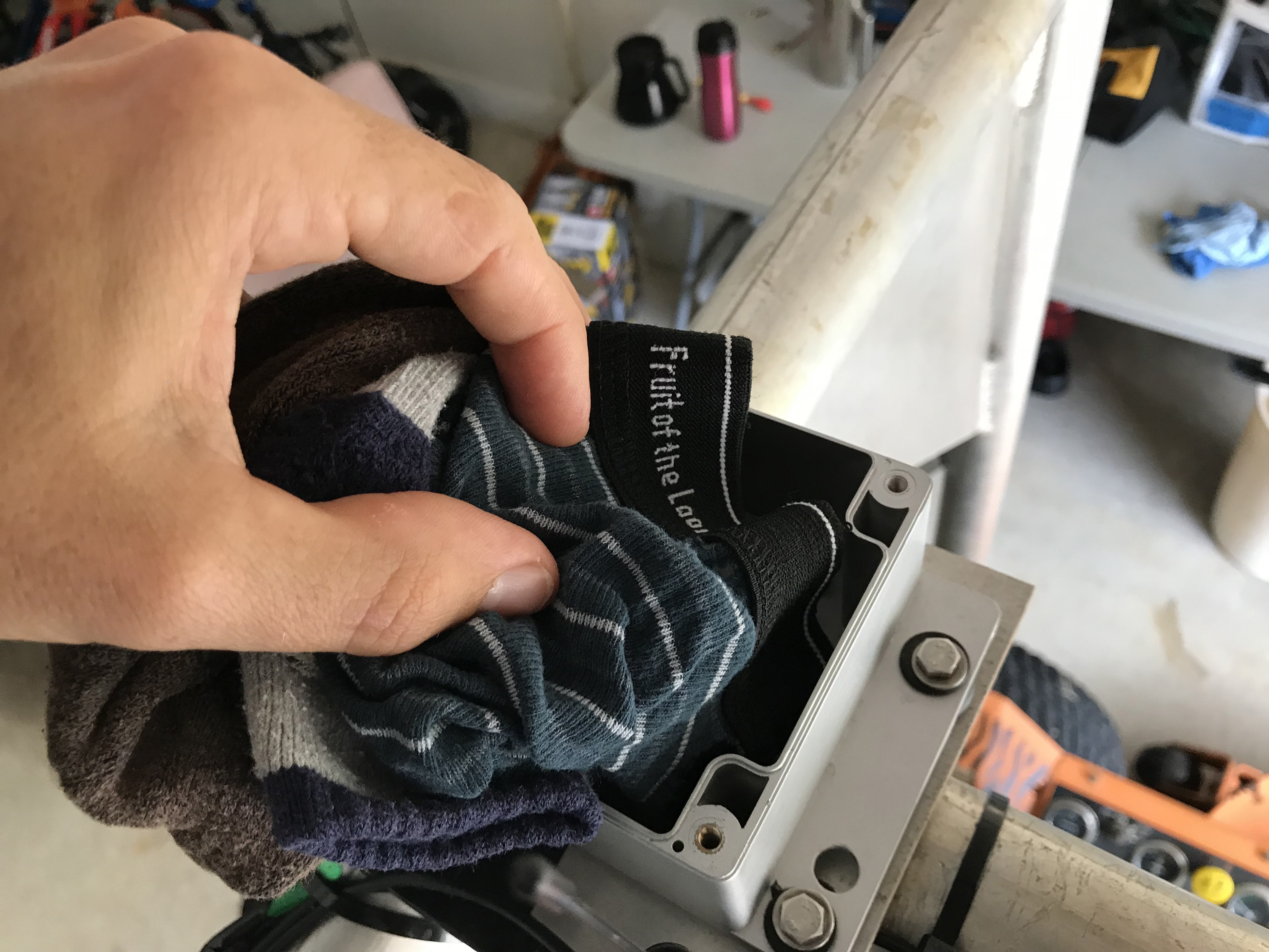
Compass Enclosure Insulation
At this point I’m sure you’re on the edge of your seat to find out what kind of wizardry is happening within the silver compass enclosure in the center of the roll bar. Well, my friend, your wait is almost over.

Since we’ve now broached the sensitive subject of compasses (or “magnetometers” / “mags” if that suits your fancy), let’s go ahead and cover one last important piece of information about this build — we’ve made a minor change to the ArduPilot source to enable fine-tuning the compass. Don’t worry, I think you’ll find that compiling & rolling your own changes to ArduPilot is a relatively painless operation.
ArduPilot Fork with Compass Offset Configuration
Inexpensive, readily-available (albeit now discontinued) Honeywell HMC5883L compasses can provide solid heading readings at high frequency, but you have to keep a few considerations in mind:
- They don’t respond well to sudden temperature fluctuations (i.e. you need to insulate your compass from sudden temperature changes (think sun suddenly pops out from behind the clouds)) — on the big Scag I’ve just stuffed the compass box full of random cloths (as insulation) and stuck some aluminum foil on top to mitigate the effects of a sudden external temperature shift often caused by the the sun’s appearance. The more standard (and committal) way of insulating the compass would involve entombing the little board (after you’ve soldered wires to communicate with it and said your last goodbyes) in some thermally insulating electronic potting compound — like this cheap stuff that most people buy or the MG Chemicals stuff you buy if your customer needs a little more traceability. Another hack if you like hacks is to mount the little fella in the enclosure, wire him up, and then pump the enclosure full of hot glue (recommended if you’re one of us who find squeezing out big globs of hot glue to be oddly therapeutic — also recommended if you’re trying to wean off a Dr. Pimple Popper addiction that the wife finds repulsive).
- They’re very sensitive to iron (of course) and this may sneak up on you — for instance, if you get within a couple of meters of a wire fence or a metal gate it can throw off your heading reading by several degrees.
- Their notions of North / South / East and West all need calibration beyond what is presently available in Ardupilot. I take care of this by enabling you to enter N-S-E-W offsets in the Ardupilot codebase fork we discuss below.
Compiling Ardupilot Source Does Not Require a PhD
So I’ve forked the official ArduPilot source and added a little bit of code to allow the user to set offsets for North/South/East/West.
Great, you say, but no-one wants to spend 2 days figuring out how to compile and load some custom autopilot code. Agreed — and fortunately compiling this code and loading it onto your Pixhawk4 / (other flight controller) is a pretty straightforward procedure.
If you’re using a Mac, this is the entire set of commands (assuming 1. you have git installed and 2. you have your flight controller connected via USB to your Mac and 3. your flight controller is Pixhawk4 (if it’s some other board, I’ll cover you in one second)):
git clone https://github.com/waynebaswell/ardupilot.git ardupilot-baswell
cd ardupilot-baswell
git submodule update --init --recursive
./waf configure --board Pixhawk4
./waf rover
./waf --target bin/ardurover --upload
If you’re running some board other than Pixhawk4, then run this command (from the ardupilot-baswell directory) to print waf configure help:
./waf configure -h
Scroll down through that big beautiful nicely-formatted help text until you see help for the --board option, i.e.:

In a world full of caveats, alas ArduPilot builds are no exception. Recently ArduPilot has moved to a new base firmware called ChibiOS (that, among other advantages, greatly simplifies the code required to port ArduPilot to new boards).
And so, if instead of Pixhawk4 you’re running Pixhawk2/Cube (please proceed with caution as I haven’t tested this code on a Pixhawk2), you may be tempted to use one of the Cube.. board options above — but those options are actually supporting the old base firmware.
A quick review of the highly informative official ArduPilot build instructions indicates that we’d use the following waf command to configure Pixhawk2/Cube using ChibiOS:
./waf configure --board fmuv3
Fine-Tuning the Compass
OK, now that we’ve got this custom ardupilot fork loaded, how are we going to use it to fine tune our compass? Here’s how it plays out — go outside with your robot and point it due North. Now assume you’re quite certain that the robot is pointed due North (0°) but Ardupilot is telling you you’re at 1°. So our ArduPilot fork gives you a way to go into Mission Planner and set a parameter to indicate that the compass’s notion of North is actually 1° wrong. OK, make a note of that 1 degree — we’ll use it in a bit. Now pivot your robot so that it’s pointing due East (90°) — suppose that ArduPilot is indicating 96° here — make a note of that too. So you point due South (180°) and Mission Planner indicates 174° — note this. And lastly you aim due West (270°), but Mission Planner proudly indicates 266.5° — record this as well.
Note that on our big Scag, when we engage the blades it has a slight effect on the compass (even though the compass is almost 2 meters away from the blades). In order to get the heading as close to true as possible, we always keep the blades engaged when running this compass-tuning exercise.
Here is a summary of the observations we just recorded:
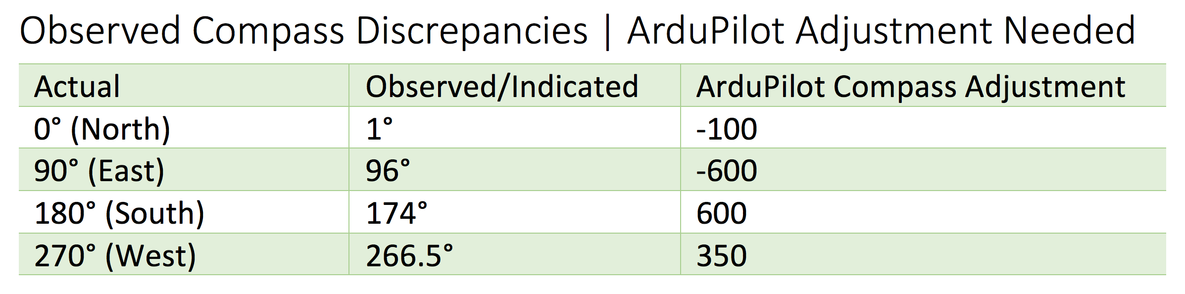
And now, assuming you’re running the waynebaswell/ardupilot fork (or you’re some future reader finding this article after this code has been merged into the main branch), you’re going to bring up Mission Planner –> Config/Tuning –> Full Parameter Tree –> AHRS and record the offsets we need (in centidegrees) in the AHRS_OFFSET parameters like this:

Don’t forget to click “Write Params” to instruct Mission Planner to save the changes to your autopilot. Now if you take your robot back outside and point North, it should be true — or at least very close to true. Go ahead and do a sanity check on North-South-East-West with your robot.
If you’re following along on this build and you’d like to compare your ArduPilot parameters with the big Scag’s ArduPilot params, you can find the current parameter file attached at this end of this post.
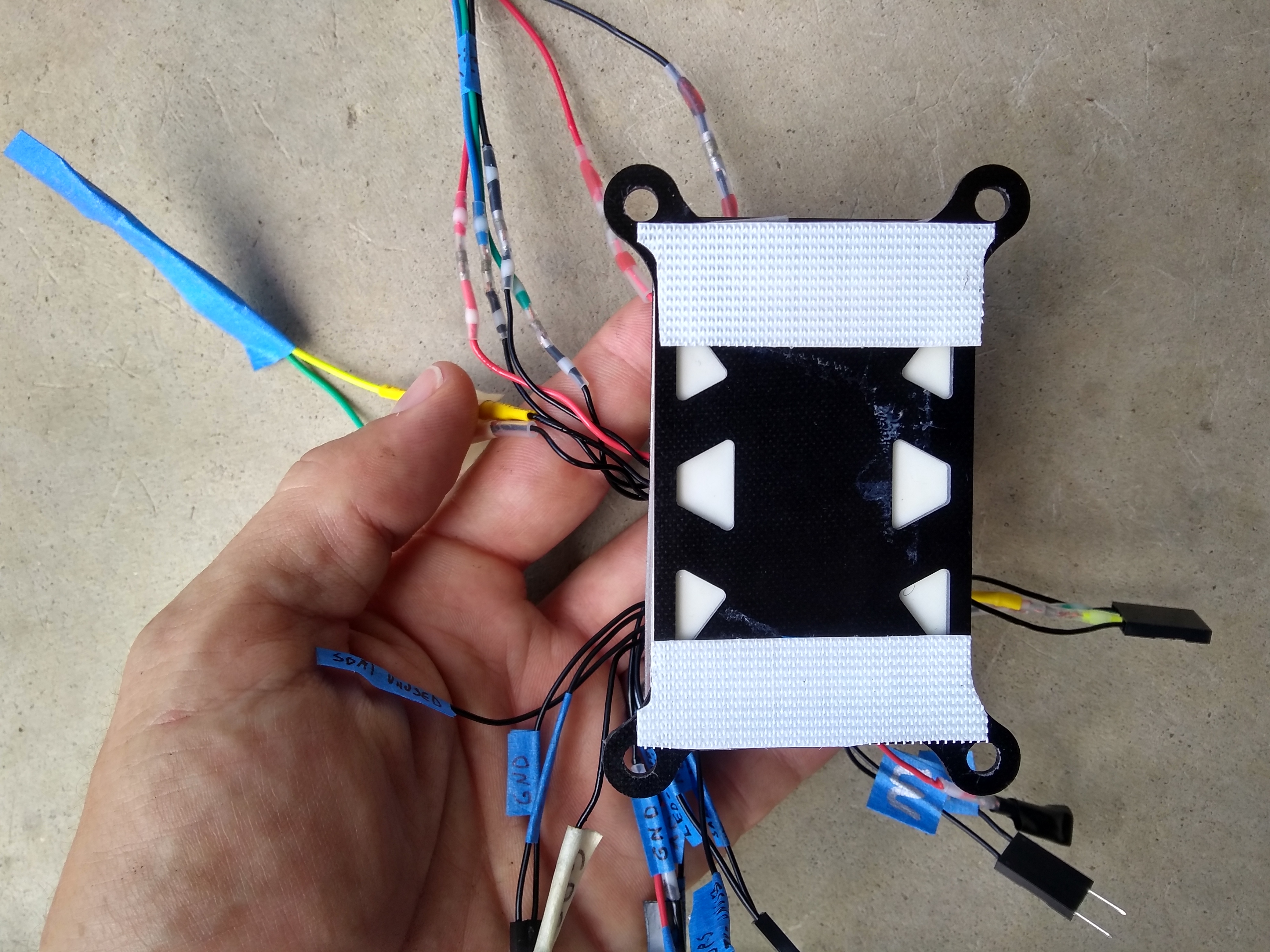
Disabling the Internal Compass
The internal compass (in the Pixhawk 4 beneath the floor pan) is surrounded by way too much static steel and swinging blades to provide useful information. Here is what the Compass settings look like in Mission Planner:
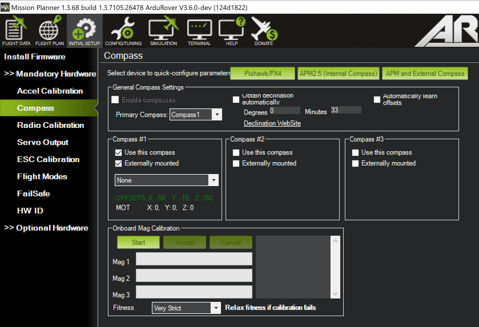
With these adjustments in place you should be able to get really solid heading readings out of a remarkably inexpensive mag.
The Finished Product
If you build robots you know that you’re never really finished — but the huge ArduPilot mower is performing quite well these days on increasingly long missions. Let’s wrap up the build description with a pic and a vid.

Here’s to Pops
You may have noticed that Pops made a slight cameo in the servo-danger-scenario pictures earlier — the truth is that most of the cool mechanical engineering on this linkage and, well, throughout this entire blog is largely either his thinking or the result of bouncing ideas off him. He used to run a big vessel fabrication shop, but now he has settled into teaching youngsters how to weld at the local High School. Not surprisingly, his students routinely take the lion’s share of trophies for craftsmanship quality at welding competitions.
Concluding Thoughts
Hopefully this little overview of an autonomous mower design helps out some future traveler.
If so, the words of Fred Brooks (in his great book) mirror your author’s thoughts:
Soli Deo gloria — To God alone be glory.
Your servant,
Roby
Footnotes
- This is not at all a criticism of the efforts from those wise men almost 15 years ago — linear actuators were likely just fine for the controlled tests they were performing — besides, pulling off that conversion in the days of early-2000s internet is quite an achievement.
- Grandma’s old adage that The Internet Doesn’t Forget apparently applies to everything except technical documentation and prior software/firmware versions.
- If future readers end up needing to run these servos at 24v on an existing 12v system, just grab a 24v Step Up Converter with sufficient amperage rating.
- Aspiring gardeners who were too busy in their youth swimming in Grandpa’s pond to help out with the tomato plants will find a wonderful primer in Charles Wilber’s nearly immaculate explanation of his methods. The late Wilber’s masterpiece is marred only by the publisher’s decision to contract out the book’s cover design to the guy who creates the packaging for all those As Seen on TV products. The book’s picture on Amazon looks goofy, but rest assured that the raving reviews of it’s content are legit and warranted. Modern readers will note that Wilber was several decades ahead of the popularity curve in his commitment to organic gardening (with a few exceptions) and treating the Earth with care.
- Readers with understandable-but-hazardous superbike addictions may add several whole numbers to their probability of survival by giving at least a few afternoons to consider David Hough’s classic guide. To this day, thanks to Mr. Hough, when I’m driving down the road and see a car (hopefully) stopping / waiting at a stop-sign on a perpendicular road up ahead, I remember his counsel to look at the very top of that vehicle’s front wheel for an additional clue about whether that driver has seen you (being overlooked is the huge danger for motorcyclists). Hough’s reasoning is simple: when a vehicle at rest begins to move, human eyes will usually detect the rotation of the wheel before registering the relatively-small motion of the large vehicle’s body.
61 Responses
This is amazing documentation! Thank you.
Thank you Vincent!
Roby,
Excellent work sir, this is an incredible rig. Well done!
Regarding the 3 and 9 o’clock locking danger, what if you mechanically limited the rotation of the servo so it couldn’t bind up at those positions?
I’m picturing a plate bolted to your hub that would run into pins or maybe bolts sticking out of the plate the servo is mounted to. Position them so they are at 9:30 and 2:30, or thereabouts. Using the software to tune them so they don’t overtravel works, but having a mechanical stop seems safer, imho.
I’ve had enough bad luck with compasses that I’ve given up on them altogether. My robot has wheel encoders coupled with an RTK gps. This works at least as well as a compass for heading, but you do have to travel is short distance in a random direction to “acquire” your heading.
I’ve heard talk of using two identical GNSS receivers to calculate heading using a vector between the two. I am going to head down this path with my build. The compass forces you to have a huge mast, and at least on my robot, that constraint ends up being a pain in the rear.
One other question, Kenny Trussell on the Ardupilot forum reported a strange compass anomaly where firing up his mower caused the compass to drift something like 20 degrees off. Did you experience that phenomenon? Kenny speculated it was the spinning blades on the mower interacting with the earth’s magnetic field.
Thank you for your kind words Drew.
I like your idea of a mechanical limit on the servo rotation — this feels like the right call.
100% agreed that compasses can be a real sore spot in ArduPilot — for instance, I think there is a bug (well, or was a bug if it’s now been fixed) such that, if you have 2 compasses and the first compass fails then ArduPilot will failover to your second compass but apply the magnetic offset numbers from the first compass to the second — I’ve often seen behavior like that (the tale tale sign is, for instance, your robot is running along following a beautiful 0° heading, it hits a bump and Mission Planner flashes the dreaded “Error Compass Variance” and your due-north pointed robot now registers 342° in Mission Planner). Of course, I don’t mean this is as a gripe against ArduPilot — I’ve been too lazy to just figure out where the glitch is in the source and fix it.
Thanks for pointing out Kenny’s experience — I’ve had similar (albeit less significant) behavior. For example, when you run the blades on the big Scan it can affect the overhead compass by ~2.5°. Just updated the section on compass calibration to point this out.
Look forward to seeing more updates (and slick diagrams!) on your project soon!
–Roby
How did the wheel encoders. Work out for you?
Thank again, this is one of the most best writeups I seen in a long time. I do suggest one cheap addition to your electronics list. A servo power isolator http://www.protekrc.com/2015/05/28/protek-rc-servo-power-isolator and a second power source for the flight controller and associated electronics. I have had all sorts or voltage spikes and brownouts from the mowers electrical system that sidelined my mower, and my budget, a few times. It will keep your robot safe and mowing for a long time to come.
Thanks Vincent! Good call on getting the power isolated — the unfortunately-familiar aroma of a burned board can test even the most even-tempered man’s fortitude.
“I recently brought home to the rolling-but-understanding-and-beautiful eyes of the wife”
I feel your pain.
John we just gotta remember to occasionally bring home some flowers for the Mrs. to offset the robot madness!
i would thing golf courses would be interested in autonomous mowers?
Definitely — golf courses and landscape maintenance have been the big prize for autonomous mowing solutions — historically the costs (think tens of thousands USD a few years ago…but down to +- 2000USD in 2019) made the cost/benefit impractical.
https://www.therobotreport.com/left-hand-robotics-funding-mowing-plowing-robot/
Love this build! Our first retrofit kit to automate a commercial mower used a servo with a slotted disc to allow manual operation, but we’ve moved to an electromagnetic clutch that can be overridden just by cutting power: it immediately releases. Also, if you want to move to ROS instead of Ardupilot, we’ve opensourced our boustrophedon planner (our first prototype used ardupilot planner to plot a survey), and then we ended up building this planner that can handle polygons better, and plot points without having to set the overlap to 0 (i.e. stay inside the boundary!) Would be happy to help you convert it over, and provide some ROS help if you or anyone else needs it. Check us out over at https://www.greenzie.com/ We have automated an ExMark stand-on, and a Greenworks Commercial (electric) stand-on (stand-ons are an easier platform to jump back on should they require override, IMHO), but that 72″ deck is impressive.
Hi Charles! Thanks for stopping by — will be closely following Greenzie’s progress and growth — you guys are making me think that ATL is gearing up to challenge Austin’s status as the de-facto New Silicon Valley.
Hi Roby,
Thank you for this excellent knowledge! Please keep it coming! Maybe this already exists, but is there a forum to share this precision GPS autonomous mower experience? That would allow us newbies can come up the curve faster and maybe allow us all to skip reinventing the wheel? The ROS help from Charles Brian Quinn sounds great!
Thanks,
Mike W
Hi Mike! The ArduPilot forums have the biggest group of folks working on mowers that I know. Keep in mind that ArduPilot and ROS have important licensing differences such that, while ArduPilot has a huge following for this kind of application, it may make more sense for a business to use ROS/PX4 so that they aren’t legally bound to open-source their changes to the flight controller code.
Are the controls spring-loaded to neutral? What happens if you lose power (or signal) to a servo – will it hold at its current setting?
Hi Mike! You bring up an important point — if power is lost to the servos they stay at their current position (in the configuration described in this post). I would sleep better with some kind of weak-but-steady spring pushing the handles to the middle. Hopefully, at a minimum, in a not-so-distant post we can cover obstacle detection and anomaly disarm/shutdown.
Super job!!
Thank you Eigertec!
Hey Roby, this is very cool. It looks like you are using a RTK based GPS system with the pixhawk navigation, are you using the RTK system from SwiftNav? Do you have any sensors for obstacle detection/avoidance? I’ve seen some guys that use a Lidar based system for that. I know a guy up in Missouri and a company on Colorado that are doing stuff like that, I’m sure there are others. I converted my Scagg into an RC based system with FPV. I thought about trying for autonomy, but my property is a very challenging cut, ideally I’d like the ability to hand off between full autonomy & manual RC control. It would be very cool if I could drive around a perimeter to create a geo-fenced area and then hand off to the mower to cut in the defined area & detect/avoid obstacles, but with all the trees/flowerbeds we have, that would be quite a challenge. I’m ok with being able to cut remote & put the video up on the TV in the house for now, but I’d still like to take a shot at full autonomy.
I ended up completely removing my mower’s arms & seat. I have the servos connect directly to the rocker arms of the hydrostatic drives via a turnbuckle type push rod with clevis connectors on both ends, one attached to the servo arm and the other to the drive rocker arm. I also have a small servo that I can use to engage the carburetor choke so I can start the engine. I use a high power actuator to engage the hand brake when the mower is in ‘park’. I can start/stop the engine, engage/diusengage the blades all remotely. I have a range failsafe programmed into the RC receiver to turn off the engine if it loses comm with the controller. I also have a last resort bit reg mushroom smash button that will cut off the engine manually, hope I never have to use that. I modified the two joysticks of my RC controller to both spring back to center, which are calibrated to the servo neutral position, so all I need to do is let go of both joysticks and the mower will stop. Controlling it with two joysticks is very much like manually riding the mower & using the standard control arms.
Check out my demo. It looks like you are in Austin, I’m in Dallas, if you’re ever up here, give me a holler. BTW, I’m a SW engineer by profession working in embedded development my whole career, so all that technical info was much appreciated.
https://youtu.be/S4SqXmJ1Hmg
Later,
Ron
Hi Ron,
Your FPV Scag video is very slick — also that’s a beautiful piece of land.
Have you considered doing a write-up (or at least posting pictures of the components you described above) on your build anywhere? I think a lot of folks would benefit from the untold hours of engineering you clearly put in to get your setup so polished.
The rover in this post is using the u-blox ZED-F9P RTK.
We didn’t cover obstacle detection in this article, but hope to get a big post on obstacles out before too long (i.e. including Intel RealSense).
Thanks for stopping by & sharing the video!
–Roby
Nice RON. Roby here’s were I’m at now.
Just waiting for a contact block for the e-stop switch to kill the engine
We need to be careful or we will put “Husbands” out of a job!
https://www.youtube.com/watch?v=3rfqkCNxpKM
Hi John I like your progress!
Where did you purchase your front swivel wheels?
Hey John, very cool, I’m using several SPST & DPDT RC controlled relay switches from Dimension Engineering to emulate the various relay settings for the ignition system and to engage/disengage the blades & hand brake, headlights etc. You might want to check those out if you are looking a some simple way for remote start/stop. Watch out for the neighborhood pets!! 🙂
Hey Roby!
Cool project, but I just wanted to let you know something about those actuators you said weren’t safe… The linear actuators in the image from the SCAG mower actually have a magnetic clutch. If they lose power, the linear actuators disengage, and can return to neutral under the spring power of the mower arms, bringing the mower to a stop. They are from Actus Manufacturing, and can be found here: https://www.actusinc.com/erc-linear
Full disclosure, I do work for Actus and have seen videos of the SCAG Mower in action. The actuators themselves do tend to heat up when used as a servo like this, but with some heatsinking, I believe they could work for this application!
Hi Actus,
Thank you for stopping by & weighing in!
Roby,I got the whole mower just like that. You can get just the wheels only on ebay. search lawnmower swivel wheels.
I search craigslist and Facebook marketplace. You just have to be fast there is alot of guys who buy and fix up mowers.
I has electric start too, Its a cool feature as the mower can move to its start location then start by itself I alsoo have the engine kill switch on a NO relay so i it need power to close for safety.
I’m currently making a controller from arduino and Xbees. As i got tired of trying to connect my Spectrum rc controller to the Pixhawk4.
I’ll eventually switch the controller to a SBC cause i want to run ROS for image processing.
A camera like this https://www.stereolabs.com/zed/
Best part is the rear tires i got them on sale at farm and fleet brand new. Rims came from craigslist I machined and welded in a 17mm hub for the wheelchair motors.
More pictures Instagram
I’m onecaveman
Nice, good work John!
John,
Not sure what the hole pattern in your wheels looks like, but these hubs are 17mm ID and work with my wheelchair motors. Just a thought. ~$45 a piece is a bit high for my taste though.
https://hobby.npcrobotics.com/store/npc-ph817/
Food for thought.
very cool build
Thank you Bob!
Hi Roby. Thanks for posting this. I’m a bit confused though by which flight controller you use. Why are you using both a Pixhawk 4 and a Kakute F7? Should it not be possible to run Ardupilot on the Kakute F7 alone?
Thanks in advance?
Morten
Hi Morten,
You are correct — you run on either the Pixhawk 4 or the Kakute F7 alone (or whatever ArduPilot Flight Controller you prefer).
The big scag is running on a Pixhawk 4 — it’s not using a Kakute at the moment.
Here’s what happened: while I was putting together this blog post, the slick little Kakute F7 arrived and I started playing with it and got super-excited about it’s build/component quality, lack of internal mag (internal mags have been a source of enduring frustration for these big iron-laden bots), and quite-reasonable ~50USD price point. So you see, I was basically showing ArduPilot build instructions for the Kakute F7 because I figured on the next build I’ll probably switch over to the Kakute. Apologies for the confusion 🙂
Take Care,
Roby
Ooh I see. Thanks for clearing that out.?
I know the feeling with these sloppy magnetometer readings. I recently bought an Adafruit BNO055 IMU, that I will use to get a good heading estimation. I know it’s a bit expensive, but it really produces good and reliable results, with the internal chip using mag, gyro and acceleration to calculate a heading. You can get both the euler angles and the quarternions from that sensor. I just dont know how to configure the heading signal so that it fits with Ardupilot yet, but i hope it is possible.
I’m absolutely new to Ardupilot. At the moment I am looking in to what board to purchase. Would you also buy the Kakute F7 today, if you were to buy a new board?
By the way, thanks for the story from the younger years about the bike and the girl. I’m down that exact same road?.
Have a nice weekend
Morten
Hi Morten,
Yes I’d go Kakute F7 with a well-insulated external compass connected.
Definitely stay the course with your girl pursuit — you know, a good lady’s value is infinitely greater that the value of even the slickest robot project 🙂
Take care,
Roby
Mr. Roby,
Did your mower have obstacle avoidance? If so, what did you use?
Sincerely,
RJ Ring
Hi Robert,
This build did not use any obstacle avoidance — it’s definitely a goal to pull together a post addressing this.
Take care,
Roby
Thank you!
This is fantastic! I am quite a fan!
Currently working on a front deck mower for Ag applications. Currently driving in squares to tune everything in. I am using a single channel RTK HERE+ system. I am hoping to achieve precision and keep a straight line (+- 12″).
Keep up the awesome work, I will be checking back often for updates!
Hi Kai,
Thanks for stopping by — sounds like you’ve got a slick project — stick with it!
Take care,
Roby
Thanks for a very informative post
Hope this isn’t stupid question but how are the servo bards and electronics protected from water (sprinklers and or rain and or splash from wheels on wet grass). The reason I ask is on the pictures it doesn’t look like the area you mounted the servos is a covered location>
Hi Tom,
You are correct — the servos are exposed — if, for instance, we add a metal top/sides to the existing brackets (i.e. imagine that we’ve got the servo inside a rectangular metal enclosure) then that could serve both to protect the servos and to stiffen up the brackets.
Take care,
Roby
Roby,
Could you replace the pixhawk with an arduino or pi board?
Sincerely,
RJ Ring
Some people do an Emlid Navio hat for Raspberry Pi.
Thank you!
Roby, I had read your excellent RTK article probably 2 years ago but for some reason had not been back often to your site. Boy, what I had missed! This is great documentation of the process of converting a zero-turn to autonomous. Thank you!!
Thank you Kenny for your kind words. I’m always anxious to hear the latest updates on your big rovers!
Hi Roby
This site is amazing even going to the detail of where to get the servo plate with links that still work. I’m in the process to build a platform with the aim to achieve a 1cm accuracies. I see your videos and wanted to ask, did you achieve a 1cm accuracies in mission planner ?.
Also that schematic for the ublox module will be extremely helpful
Looking forward towards your next blog and kind regards from down under
Hi Darren,
It’s great to hear from the land down under! Is it insufferably American that I can hardly consider a day complete without hearing Men at Work’s masterpiece?
If your base station is close to your rover, you should be able to get pretty close to 1cm with the ZED-F9P. Of course the antenna’s visibility to the sky will have a big impact. Apologies for not having a schematic, but on the The Taming of the u-blox ZED-F9P post I think you’ll find some info that will get you rolling. Also, have seen some solid ZED-F9P tutorials on YouTube recently.
Take care,
Roby
Roby,
Great project!
Can you comment on top speed? In your videos it seems your running around rather slow. I’m starting to put together a project around a 72” hustler to mow a runway as well. However, I’m worried if in the end I have to have it drive to slow it might not be worth it. What kind of problems have you ran into as you have tried to increase the speed?
Multi antenna RTK AHRS, such as ardusimple’s new simplertk2B-SBC, might be a great solution for your magnetometer problems in the future.
Thanks for your time!
Hi Clayton — For the big rover I keep the speed around 3 MPH. It could probably be tuned to do fine far above that, but I rest better seeing it roll along at a leisurely pace.
Good luck with your big hustler project — if you give it a solid go I think you’ll be pleased with your results.
Take care,
Roby
Hi Roby,
I have been making some progress again on this project after my recent marriage and starting my first job. I want to thank you again for all the knowledge you have shared on your platform; it is a great resource for me as I am starting to get into robotics.
I am creating a build similar to your rover 2 setup and would like to integrate obstacle avoidance (for an added safety feature after I build the initial prototype). I saw you had changed from the Pixhawk to the Kakute f7 flight controller during this project. I have found videos to educate me on how to integrate the sensors for Pixhawk controllers, but it appears that there is less information regarding the Kakute controller. Would you still recommend using the Kakute at this time with additional upgrades such as this in the future?
Also, I am very interested in the Intel Realsense Camera. Were you still planning out putting out a video about integrating that with one of these builds?
Again, thank you for all of the information you take the time to publish. I am excited to hear what you are working on next!
Hi Roby,
Thank you so much for all the information and write ups you’ve been doing on this project. It is a tremendous wealth of knowledge and your site was one of the first that really helped me find a love for robotics. I am glad to see the autonomous lawn mower has been coming along well.
I was actually trying to build my own autonomous lawn vehicle that traverses through a field for a school project, albeit with different functionality (instead of cutting grass it fertilizes it). One thing I’ve had no luck in is getting some kind of autonomous system set up and working. I have a GPS RTK system set up, and I’m receiving ECEF coordinates of my vehicle with around 2cm of accuracy, so I know where my vehicle is precisely at all times.
However, I’m unsure how to use these coordinates to have the robot go forwards in a straight line, and then back again, and then turn for another loop around. I see that you are using ArduPilot, but I was wondering what the fundamental approach is to this, so I can maybe code up a program on my own.
Specifically, here are my two questions:
(1) How would I get a map of the boundaries of field in terms of coordinates? I know I can have the user maybe take the vehicle along the edges of the field, and save the coordinate every second. So I have an array of coordinates representing the boundary of my field. However, how would I use this array to maybe create a function to check whether or not the vehicle is within the boundary at any given time? I know how to do this if I only have 4 points marking the boundary, but not for a boundary that might have curves and edges.
(2) How would I have the vehicle go in a straight line? How can I use the GPS information to do this? Would I need a magnetometer? I’m just so lost on this part so any guidance to point me in the right direction would be appreciated.
Thank you once again for all the stuff you’ve been putting out. Its a real help to newbies like me. Anyways, good luck and I hope to hear back soon!
Cheers from Jersey,
Aditya
This is the best DIY documentation I have ever read! Thank you so much Roby! I have a silly question. How many joystick did you use? I assume you need a joystick for each arm (left and right). Is it correct? I am sure you have made a lot improvements after writing this doc. Can you have an updated version?
ty eric — just 1 joystick — ardupilot mixes the output for you.
I came across this after doing a very similar conversion to my old scag mower using many of the same components including servos. https://www.youtube.com/watch?v=cW8qgKhN_Iw
One thing I learned very quickly is the puny horn setscrews will come loose in a matter of minutes. I went ahead and welded the flange directly to the servo shaft. No more issues. The thing runs awesome.
Roby,
Boy am I impressed. have a Turf tiger and about 6 acres to mow. I am interested in building a n autonomous mower for my own use. I am thinking to set up linkage exactly like yours and use a GPS satellite plus RTK for control; like the Mammotion Luba 2 small mower. In fact, I am wondering why I can’t just take the electronics from a LUBA 2; just use a few channels like signals to drive the servos for the arms and add a few emergncy shutoff devices like bumpers.
I am thinking of this as an upcoming fall winter project. I need to locate a shop for the fabrication and a good controls engineer.
I am ready to pay for the project.
I am just looking for any help possible.
I have 2 scag dealers nearby. I was thinking about starting with them or do you have other ideas.
I am located at Lake Anna VA, about 25 mi west of Fredericksburg.
Thank you for providing a write up that a newbie can understand. What you provided and this comment section just made life difficult for my turf tiger.
Good luck Braylon 🙂